Page 3953 of 4083
INSPECTION AND ADJUSTMENTWT-7
< BASIC INSPECTION >
C
DF
G H
I
J
K L
M A
B
WT
N
O P
This procedure must be done after replacement of a low tire pressure warning transmitter or BCM.
New replacement transmitters are provided "asleep" and must first be "woken up" using Transmitter
Activation Tool J-45295 before ID registration can be performed.
1. Connect CONSULT-III.
2. Select "ID REGIST" under BCM.
3. Adjust the tire pressures to the values shown in the table and drive the vehicle at 40 km/h (25 MPH) or
more for a few minutes.
4. After completing all ID registrations, press “END” to complete the procedure.
5. Inflate all tires to proper pressure. Refer to WT-51, "
Tire".
Tire position
Tire pressure kPa (kg/cm2, psi)
Front LH 250 (2.5, 36)
Front RH 230 (2.3, 33)
Rear RH 210 (2.1, 30)
Rear LH 190 (1.9, 27)
Activation tire position CONSULT-III
Front LH “YET”↓
“DONE”
Front RH
Rear RHRear LH
Revision: March 2010 2008 QX56
Page 3954 of 4083

WT-8
< FUNCTION DIAGNOSIS >
TPMS
FUNCTION DIAGNOSIS
TPMS
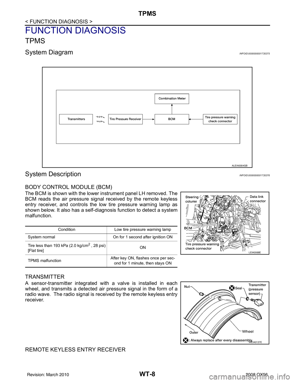
System DiagramINFOID:0000000001735375
System DescriptionINFOID:0000000001735376
BODY CONTROL MODULE (BCM)
The BCM is shown with the lower instrument panel LH removed. The
BCM reads the air pressure signal received by the remote keyless
entry receiver, and controls the low tire pressure warning lamp as
shown below. It also has a self-d iagnosis function to detect a system
malfunction.
TRANSMITTER
A sensor-transmitter integrated with a valve is installed in each
wheel, and transmits a detected air pr essure signal in the form of a
radio wave. The radio signal is received by the remote keyless entry
receiver.
REMOTE KEYLESS ENTRY RECEIVER
ALEIA0004GB
Condition Low tire pressure warning lamp
System normal On for 1 second after ignition ON
Tire less than 193 kPa (2.0 kg/cm
2 , 28 psi)
[Flat tire] ON
TPMS malfunction After key ON, flashes once per sec-
ond for 1 minute, then stays ON
LEIA0068E
WEIA0137E
Revision: March 2010 2008 QX56
Page 3991 of 4083
WHEELWT-45
< ON-VEHICLE MAINTENANCE >
C
DF
G H
I
J
K L
M A
B
WT
N
O P
ON-VEHICLE MAINTENANCE
WHEEL
InspectionINFOID:0000000001534676
1. Check tires for wear and improper inflation.
2. Check wheels for deformation, cracks and other damage. If deformed, remove wheel and check wheel runout.
a. Remove tire from wheel and mount wheel on a tire balance machine.
b. Set dial indicator as shown. Refer to WT-51, "
Road Wheel" .
3. Check front wheel bearings for looseness.
4. Check front suspension for looseness.
SFA975B
Revision: March 2010 2008 QX56
Page 3994 of 4083
WT-48
< ON-VEHICLE REPAIR >
WHEEL AND TIRE ASSEMBLY
Rotation
INFOID:0000000001534678
NOTE:
Follow the maintenance schedule for tire rotation service intervals. Refer to MA-29, "
Tire Rotation" .
1. Rotate the tires on each side from front to back as shown. Do not include the spare tire when rotating the tires.
CAUTION:
When installing wheel s, tighten them diagonally by dividing
the work two to three times in order to prevent the wheels
from developing any distortion.
2. Adjust the tire pressure to specification. Refer to WT-51, "
Tire" .
3. After the tire rotation, retighten the wheel nuts after the vehicle has been driven for 1,000 km (600 miles), and also after every
wheel and tire have been installed such as after repairing a flat tire. Wheel nut torque : 133 N·m (14 kg-m, 98 ft-lb)
SMA829C
Revision: March 2010
2008 QX56
Page 3995 of 4083

REMOVAL AND INSTALLATIONWT-49
< REMOVAL AND INSTALLATION >
C
DF
G H
I
J
K L
M A
B
WT
N
O P
REMOVAL AND INSTALLATION
REMOVAL AND INSTALLATION
Transmitter (Pressure Sensor)INFOID:0000000001534679
REMOVAL
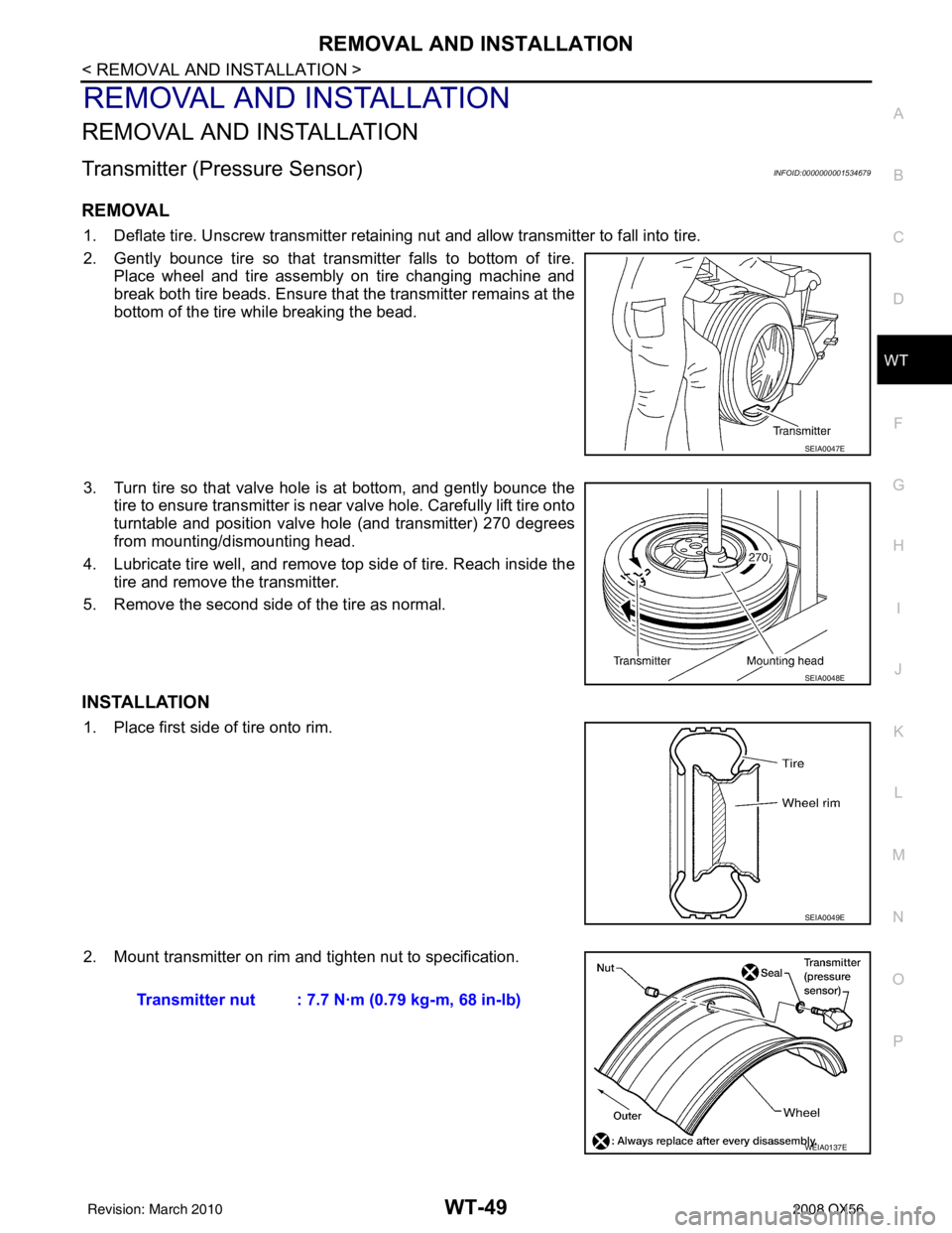
1. Deflate tire. Unscrew transmitter retaining nut and allow transmitter to fall into tire.
2. Gently bounce tire so that transmitter falls to bottom of tire. Place wheel and tire assembly on tire changing machine and
break both tire beads. Ensure that the transmitter remains at the
bottom of the tire while breaking the bead.
3. Turn tire so that valve hole is at bottom, and gently bounce the tire to ensure transmitter is near valve hole. Carefully lift tire onto
turntable and position valve hole (and transmitter) 270 degrees
from mounting/dismounting head.
4. Lubricate tire well, and remove top side of tire. Reach inside the tire and remove the transmitter.
5. Remove the second side of the tire as normal.
INSTALLATION
1. Place first side of tire onto rim.
2. Mount transmitter on rim and tighten nut to specification.
SEIA0047E
SEIA0048E
SEIA0049E
Transmitter nut : 7.7 N·m (0.79 kg-m, 68 in-lb)
WEIA0137E
Revision: March 2010 2008 QX56
Page 3996 of 4083
WT-50
< REMOVAL AND INSTALLATION >
REMOVAL AND INSTALLATION
3. Place wheel on turntable of tire machine. Ensure that transmitteris 270 degrees from mounting/dismounting head.
NOTE:
Do not touch transmitter with mounting head.
4. Lubricate tire well, and install second side of tire as normal. Ensure that tire does not rotate relative to rim.
5. Inflate tire and balance the wheel and tire assembly. Refer to WT-46, "
Adjustment" .
6. Install Wheel and tire assembly in appropriate wheel position on vehicle.
NOTE:
If replacing the transmitter, then transmitter wake up operation
must be performed. Refer to WT-5, "
Transmitter Wake Up Operation" .
7. Adjust neutral position of steering angle sensor. Refer to BRC-8, "
ADJUSTMENT OF STEERING ANGLE
SENSOR NEUTRAL POSITION : Special Repair Requirement" .
SEIA0048E
Revision: March 2010 2008 QX56
Page:
< prev 1-8 9-16 17-24