Page 2174 of 4083

GI-32
< PRECAUTION >
TOW TRUCK TOWING
TOW TRUCK TOWING
Tow Truck TowingINFOID:0000000004900863
WARNING:
• Never get under the vehicle while it is supported only by the jack. Always use safety stands to sup-
port the frame when you have to get under the vehicle.
• Place wheel chocks at both front an d back of the wheels on the ground.
CAUTION:
• All applicable local laws regarding the towing operation must be obeyed.
• It is necessary to use proper towing equipment to avoid possible damage during towing operation.
Towing is in accordance with Towing Procedure Manual at dealer.
• Always attach safety chains before towing.
• When towing, make sure that the transmission, steering system and power train are in good order. If
any unit is damaged, dollies must be used.
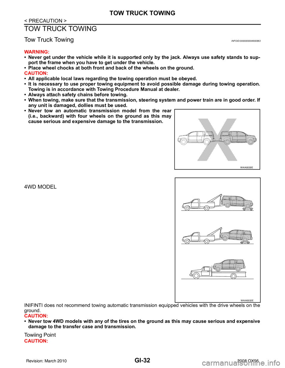
• Never tow an automatic transmission model from the rear
(i.e., backward) with four wh eels on the ground as this may
cause serious and expensive dama ge to the transmission.
4WD MODEL
INIFINTI does not recommend towing automatic transmi ssion equipped vehicles with the drive wheels on the
ground.
CAUTION:
• Never tow 4WD models with any of the tires on the ground as this may cause serious and expensive
damage to the transfer case and transmission.
Towiing Point
CAUTION:
WAIA0030E
WAIA0032E
Revision: March 2010 2008 QX56
Page 2176 of 4083

GI-34
< BASIC INSPECTION >
SERVICE INFORMATION FOR ELECTRICAL INCIDENT
BASIC INSPECTION
SERVICE INFORMATION FOR ELECTRICAL INCIDENT
Work FlowINFOID:0000000001539223
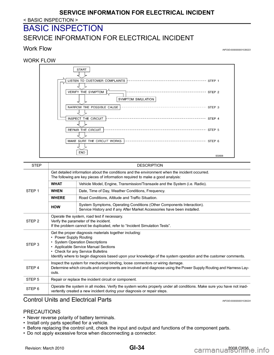
WORK FLOW
Control Units and Electrical PartsINFOID:0000000001539224
PRECAUTIONS
• Never reverse polarity of battery terminals.
• Install only parts specified for a vehicle.
• Before replacing the control unit, check the i nput and output and functions of the component parts.
• Do not apply excessive force when disconnecting a connector.
SGI838
STEP DESCRIPTION
STEP 1 Get detailed information about the conditions and the environment when the incident occurred.
The following are key pieces of information required to make a good analysis:
WHAT
Vehicle Model, Engine, Transmission/Transaxle and the System (i.e. Radio).
WHEN Date, Time of Day, Weather Conditions, Frequency.
WHERE Road Conditions, Altitude and Traffic Situation.
HOW System Symptoms, Operating Conditions
(Other Components Interaction).
Service History and if any After Market Accessories have been installed.
STEP 2 Operate the system, road test if necessary.
Verify the parameter of the incident.
If the problem cannot be duplicated, refer to “Incident Simulation Tests”.
STEP 3 Get the proper diagnosis materials together including:
• Power Supply Routing
• System Operation Descriptions
• Applicable Service Manual Sections
• Check for any Service Bulletins
Identify where to begin diagnosis based upon your knowledge of the system operation and the customer comments.
STEP 4 Inspect the system for mechanical binding, loose connectors or wiring damage.
Determine which circuits and components are involved and diagnose using the Power Supply Routing and Harness Lay-
outs.
STEP 5 Repair or replace the incident circuit or component.
STEP 6 Operate the system in all modes. Verify the system works properly under all conditions. Make sure you have not inad-
vertently created a new incident during your diagnosis or repair steps.
Revision: March 2010
2008 QX56
Page 2188 of 4083

GI-46
< BASIC INSPECTION >
CONSULT-III CHECKING SYSTEM
CONSULT-III CHECKING SYSTEM
DescriptionINFOID:0000000001539228
• When CONSULT-III is connected with a data link connectorequipped on the vehicle side, it will communicate with the control
unit equipped in the vehicle and then enable various kinds of diag-
nostic tests.
• Refer to “CONSULT-III Operation Manual” for more information.
Function and System ApplicationINFOID:0000000001555032
1 : Hood release handle
2 : Data link connector
ALBIA0047ZZ
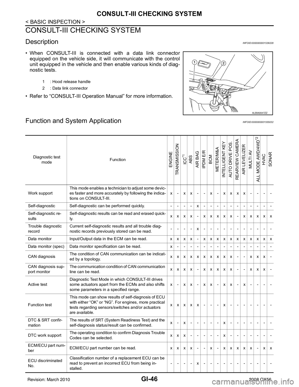
Diagnostic test mode Function
ENGINE
TRANSMISSION
ICC
*1
ABS
AIR BAG
IPDM E/R
BCM
METER/M&A
INTELLIGENT KEY
AUTO DRIVE POS.
REARVIEW CAMERA
AIR LEVELIZER MULTI AV
ALL MODE AWD/4WD
*2
HVAC
SONAR
Work support This mode enables a technician to adjust some devic-
es faster and more accurately by following the indica-
tions on CONSULT-III. x - xx - - x - xxxx - - - -
Self-diagnostic Self-diagnostic can be performed quickly. ----x-----------
Self-diagnostic re-
sults Self-diagnostic results can be read and erased quick-
ly.
xxxx - xxxxx - xxxxx
Trouble diagnostic
record Current self-diagnostic results and all trouble diag-
nostic records previously stored can be read.
--- - x--- - -------
Data monitor Input/Output data in the ECM can be read. xxxx - xxxxxxxxxxx
Data monitor (spec)Data monitor specification can be read. x---------------
CAN diagnosis The condition of CAN communication can be indicat-
ed by a topology.
xxxxxxxxxx - - xxx -
CAN diagnosis sup-
port monitor The communication condition of CAN communication
line can be read.
xxxx - xxxxx - - xxx -
Active test Diagnostic Test Mode in which CONSULT-III drives
some actuators apart from the ECMs and also shifts
some parameters in a specified range. x-xx-xx-xx-x- - - -
Function test This mode can show results of self-diagnosis of ECU
with either “OK” or “NG”. For engines, more practical
tests regarding sensors/switches and/or actuators
are available. xxxxx - - - x
-------
DTC & SRT confir-
mation The results of SRT (System Readiness Test) and the
self-diagnosis status/result can be confirmed.
x-x-----x-------
DTC work support The operating condition to confirm Diagnosis Trouble
Codes can be selected. xxx-----x-------
ECM/ECU part num-
ber ECM/ECU part number can be read.
xxxx - - x - xxxxx - xx
ECU discriminated
No. Classification number of a replacement ECU can be
read to prevent an incorrect ECU from being in-
stalled.
----x-----------
Revision: March 2010
2008 QX56
Page 3233 of 4083
![INFINITI QX56 2008 Factory Service Manual U1010 CONTROL UNIT (CAN)SEC-25
< COMPONENT DIAGNOSIS > [WITH INTELLIGENT KEY SYSTEM]
C
D
E
F
G H
I
J
L
M A
B
SEC
N
O P
U1010 CONTROL UNIT (CAN)
DescriptionINFOID:0000000001539119
CAN (Controller Area INFINITI QX56 2008 Factory Service Manual U1010 CONTROL UNIT (CAN)SEC-25
< COMPONENT DIAGNOSIS > [WITH INTELLIGENT KEY SYSTEM]
C
D
E
F
G H
I
J
L
M A
B
SEC
N
O P
U1010 CONTROL UNIT (CAN)
DescriptionINFOID:0000000001539119
CAN (Controller Area](/manual-img/42/57030/w960_57030-3232.png)
U1010 CONTROL UNIT (CAN)SEC-25
< COMPONENT DIAGNOSIS > [WITH INTELLIGENT KEY SYSTEM]
C
D
E
F
G H
I
J
L
M A
B
SEC
N
O P
U1010 CONTROL UNIT (CAN)
DescriptionINFOID:0000000001539119
CAN (Controller Area Network) is a serial communication line for real time applications. It is an on-vehicle mul-
tiplex communication line with high data communicati on speed and excellent error detection ability. Modern
vehicle is equipped with many electronic control unit, and each control unit shares information and links with
other control units during operation (not independent). In CAN communication, control units are connected
with 2 communication lines (CAN-H line, CAN-L line) allowing a high rate of information transmission with less
wiring. Each control unit transmits/receives data but selectively reads required data only.
CAN Communication Signal Chart, refer to LAN-44, "
CAN Communication Signal Chart".
DTC LogicINFOID:0000000001539120
DTC DETECTION LOGIC
Diagnosis ProcedureINFOID:0000000001539121
1.REPLACE INTELLIGENT KEY UNIT
When DTC [U1010] is detected, replace Intelligent Key unit.
>> Replace Intelligent Key unit.
Special Repair RequirementINFOID:0000000001539122
1.REQUIRED WORK WHEN REPLACING INTELLIGENT KEY UNIT
Initialize control unit. Refer to CONSULT-III Operation Manual.
>> Work end.
DTC CONSULT-III display de-
scription DTC Detection Condit
ion Possible cause
U1010 CONTROL UNIT (CAN) When detecting error during the initial diagnosis of CAN control-
ler of Intelligent Key unit. Intelligent Key unit
Revision: March 2010
2008 QX56
Page 3724 of 4083
PREPARATIONTM-177
< PREPARATION >
CEF
G H
I
J
K L
M A
B
TM
N
O P
Commercial Service ToolINFOID:0000000004917423
—
(J-47002)
Transmission jack adapter kit
1. —
(J-47002-2)
Center bracket
2. —
(J-47002-3)
Adapter plate
3. —
(J-47002-4)
Adapter block Assist in removal of transmission and transfer
case as one assembly using only one trans-
mission jack.
—
( J-46534 )
Trim tool set For removing trim
Tool number
(Kent-Moore No.)
Tool name
Description
WCIA0499E
AWJIA0483ZZ
Tool name
Description
Power tool Loosening bolts and nuts
Drift Installing manual shaft seals
a: 22 mm (0.87 in) dia.
Drift Installing rear oil seal (4WD models)
a: 64 mm (2.52 in) dia.
PBIC0190E
NT083
SCIA5338E
Revision: March 2010 2008 QX56
Page 3750 of 4083
CONTROL VALVE WITH TCMTM-203
< ON-VEHICLE REPAIR >
CEF
G H
I
J
K L
M A
B
TM
N
O P
10. Remove bolts (A), (B) and (C) from control valve with TCM.
11. Remove control valve with TCM from transmission case. CAUTION:
When removing, be careful with the manual valve notch and
manual plate height. Remove it vertically.
12. Remove the A/T fluid temperature sensor 2 or plug as shown below.
a. A/T fluid temperature sensor 2
i. Remove A/T fluid temperature sensor 2 with bracket from con- trol valve with TCM.
ii. Remove bracket from A/T fluid temperature sensor 2.
b. Plug
: Front
Bolt symbol Length mm (in) Number of bolts
A 42 (1.65) 5
B 55 (2.17) 6
C 40 (1.57) 1
SCIA8074E
SCIA5142E
SCIA5253E
SCIA5264E
Revision: March 2010 2008 QX56
Page 3754 of 4083

CONTROL VALVE WITH TCMTM-207
< ON-VEHICLE REPAIR >
CEF
G H
I
J
K L
M A
B
TM
N
O P
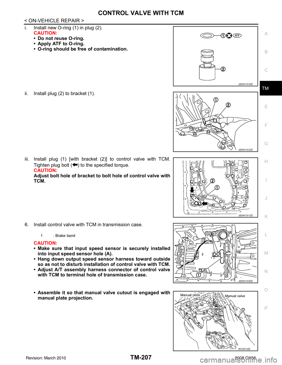
i. Install new O-ring (1) in plug (2). CAUTION:
• Do not reuse O-ring.
• Apply ATF to O-ring.
• O-ring should be free of contamination.
ii. Install plug (2) to bracket (1).
iii. Install plug (1) [with bracket (2)] to control valve with TCM. Tighten plug bolt ( ) to the specified torque.
CAUTION:
Adjust bolt hole of bracket to bolt hole of control valve with
TCM.
6. Install control valve with TCM in transmission case. CAUTION:
• Make sure that input speed sensor is securely installed
into input speed sensor hole (A).
• Hang down output speed sensor harness toward outside
so as not to disturb installati on of control valve with TCM.
• Adjust A/T assembly harness connector of control valve with TCM to terminal hole of transmission case.
• Assemble it so that manual valve cutout is engaged with
manual plate projection.
JSDIA1313ZZ
JSDIA1312ZZ
JSDIA1311ZZ
1 : Brake band
JSDIA1318ZZ
SCIA5142E
Revision: March 2010 2008 QX56
Page 3771 of 4083
TM-224
< DISASSEMBLY AND ASSEMBLY >
OVERHAUL
VK56DE models for 4WD
16. Bearing race17. Needle bearing18. Manual plate
19. Parking rod 20. Manual shaft oil seal 21. Manual shaft
22. O-ring 23. Band servo anchor end pin 24. Detent spring
25. Spacer 26. Seal ring27. Return spring
28. O-ring 29. Servo assembly30. Snap ring
31. Snap ring 32. Sub-harness33. Control valve with TCM
34. Bracket 35. A/T fluid temperature sensor 2 36. Terminal cord assembly
37. O-ring 38. Retaining pin39. Transmission case
*: Apply Genuine Anaerobic Liquid Gasket or equivalent.
Revision: March 2010 2008 QX56