Page 2482 of 4083

IP-12
< ON-VEHICLE REPAIR >
INSTRUMENT PANEL ASSEMBLY
Removal and Installation
INFOID:0000000001602122
REMOVAL
CAUTION:
Disconnect both the negative and po sitive battery terminals in advance.
1. Disconnect both negative and positive termi nals, then wait at least 3 minutes.
2. Remove front center console. Refer to IP-20, "
Removal and Installation".
3. Remove steering column assembly. Refer to ST-20, "
Removal and Installation".
4. Remove combination meter. Refer to MWI-76, "
Removal and Installation".
5. Remove instrument panel upper cover and disconnect rear sonar speaker (if equipped).
6. Remove cluster lid C. Refer to IP-15, "
Removal and Installation".
7. Remove display assembly. Refer to AV-164, "
Removal and Installation".
8. Remove instrument lower/upper panel RH and glove box. Refer to IP-17, "
Removal and Installation" and
IP-18, "
Removal and Installation".
9. Release the clips, disconnect the optical sensor harness and remove defroster grille.
10. Release the clips, disconnect the connecto rs and remove RH, LH, and center speakers.
11. Remove RH/LH front pillar finishers. Refer to INT-14, "
Removal and Installation".
12. Remove the passenger air bag module nuts and disconnect the connectors. Refer to SR-10, "
Removal
and Installation".
13. Disconnect remaining optional equipment connectors (if equipped).
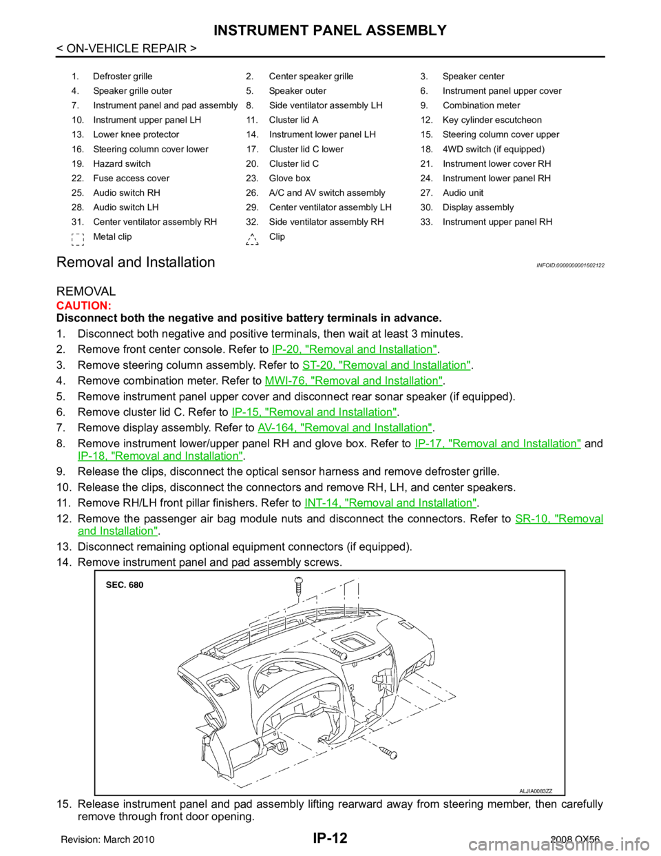
14. Remove instrument panel and pad assembly screws.
15. Release instrument panel and pad assembly lifting rearward away from steering member, then carefully remove through front door opening.
1. Defroster grille 2. Center speaker grille3. Speaker center
4. Speaker grille outer 5. Speaker outer6. Instrument panel upper cover
7. Instrument panel and pad assembly 8. Side ventilator assembly LH 9. Combination meter
10. Instrument upper panel LH 11. Cluster lid A 12. Key cylinder escutcheon
13. Lower knee protector 14. Instrument lower panel LH 15. Steering column cover upper
16. Steering column cover lower 17. Cluster lid C lower 18. 4WD switch (if equipped)
19. Hazard switch 20. Cluster lid C21. Instrument lower cover RH
22. Fuse access cover 23. Glove box 24. Instrument lower panel RH
25. Audio switch RH 26. A/C and AV switch assembly 27. Audio unit
28. Audio switch LH 29. Center ventilator assembly LH 30. Display assembly
31. Center ventilator assembly RH 32. Side ventilator assembly RH 33. Instrument upper panel RH Metal clip Clip
ALJIA0083ZZ
Revision: March 2010 2008 QX56
Page 2487 of 4083
INSTRUMENT LOWER PANEL RH AND GLOVE BOXIP-17
< ON-VEHICLE REPAIR >
C
DE
F
G H
I
K L
M A
B
IP
N
O P
INSTRUMENT LOWER PANE L RH AND GLOVE BOX
Exploded ViewINFOID:0000000001602127
Removal and InstallationINFOID:0000000001602128
REMOVAL
1. Remove the instrument lower cover RH.
⇐: Vehicle front
2. Remove the instrument lower panel RH screws.
3. Release the clips and remove instrument lower panel RH and glove box from instrument panel and pad assembly.
4. Release the clips and remove fuse access cover.
5. Remove glove box pivot pins and damper clip, then remove glove box from instrument panel RH.
INSTALLATION
Installation is in the reverse order of removal.
1. Instrument panel and pad assembly 2. Instrument lower panel RH 3. Glove box
4. Fuse access cover 5. Glove box pivot pin⇐Vehicle front
Clip
ALJIA0079ZZ
LLIA0072E
Revision: March 2010 2008 QX56
Page 2768 of 4083

PG
PG-1
ELECTRICAL & POWER CONTROL
C
DE
F
G H
I
J
K L
B
SECTION PG
A
O P
N
CONTENTS
POWER SUPPLY, GROUND & CIRCUIT ELEMENTS
PRECAUTION .......
........................................2
PRECAUTIONS .............................................. .....2
Precaution for Supplemental Restraint System
(SRS) "AIR BAG" and "SEAT BELT PRE-TEN-
SIONER" ............................................................. ......
2
Precaution Necessary for Steering Wheel Rota-
tion After Battery Disconnect ............................... ......
2
Precaution for Power Generation Variable Voltage
Control System ..........................................................
3
PREPARATION ............................................4
PREPARATION .............................................. .....4
Special Service Tool ........................................... ......4
Commercial Service Tool ..........................................4
BASIC INSPECTION ....................................5
BATTERY ....................................................... .....5
How to Handle Battery ........................................ ......5
Work Flow ........................................................... ......7
INSPECTION AND ADJUSTMENT .....................8
ADDITIONAL SERVICE WHEN REMOVING BAT-
TERY NEGATIVE TERMINAL ............................... ......
8
ADDITIONAL SERVICE WHEN REMOVING
BATTERY NEGATIVE TERMINAL : Special Re-
pair Requirement ................................................. ......
8
COMPONENT DIAGNOSIS ..........................9
POWER SUPPLY ROUTING CIRCUIT .......... .....9
Wiring Diagram — Battery Power Supply — ....... ......9
Wiring Diagram — Accessory Power Supply — .....17
Wiring Diagram — Ignition Power Supply — ....... ....21
Fuse .........................................................................29
Fusible Link .............................................................29
GROUND ...........................................................30
Ground Distribution ..................................................30
HARNESS .........................................................40
Harness Layout ................................................... ....40
ELECTRICAL UNITS LOCATION ....................62
Electrical Units Location ..........................................62
HARNESS CONNECTOR .................................65
Description ...............................................................65
STANDARDIZED RELAY .................................68
Description ...............................................................68
FUSE BLOCK - JUNCTION BOX (J/B) ............70
Terminal Arrangement .............................................70
FUSE, FUSIBLE LINK AND RELAY BOX ........71
Terminal Arrangement .............................................71
ON-VEHICLE REPAIR .................................73
BATTERY ..........................................................73
Removal and Installation ..................................... ....73
SERVICE DATA AND SPECIFICATIONS
(SDS) ............... .......................................... ...
74
SERVICE DATA AND SPECIFICATIONS
(SDS) .................................................................
74
Battery ................................................................. ....74
Revision: March 2010 2008 QX56
Page 2810 of 4083

PG
HARNESSPG-43
< COMPONENT DIAGNOSIS >
C
DE
F
G H
I
J
K L
B A
O P
N
D4 M56 W/16 : To M201
D4 M203 W/12 : A/T shift selector
A3 M57 — : Body ground D5 M205 W/32 : DVD player
F2 M58 B/6 : Intake door motor D5 M207 BR/20 : Console power socket
F3 M59 BR/2 : Glove box lamp C4 M208 BR/20 : To M69
G3 M60 W/6 : Fuse block (J/B) C5 M209 W/2: Inside key antenna 2 (rear of center
console)
C3 M61 — : Body ground C4 M210 GR/2: Inside key antenna 3 (front of center
console)
F4 M62 B/2 : Front blower motor C4 M212 W/6 : Rear heated seat switch LH
D4 M63 BR/20 : To M251 C4 M213 BR/6 : Rear heated seat switch RH
D4 M64 BR/24 : To M202 Console switch sub-harness
F2 M65 W/4 : To M301 D4 M251 BR/20 : To M63
G3 M66 BR/1 : To E33 D4 M252 BR/6 : Front heated seat switch RH
C3 M69 BR/20 : To M208 C4 M253 GR/6 : VDC OFF switch
A2 M70 W/40 : Intelligent key unit C3 M255 W/6 : Front heated seat switch LH
A2 M71 L/4 : Heated steering relay C4 M256 B/2 : A/T shift selector
D3 M73 BR/6 : Back-up lamp relay C4 M260 W/6 : Heated steering wheel switch
G3 M74 BR/24 : To D102 Optical sensor sub-harness
G3 M75 W/10 : To D101 F1 M301 W/4 : To M65
A3 M76 W/6 : Electric brake (pre-wiring) D1 M302 B/4 : Optical sensor
E2 M77 Y/4 : Front passenger air bag module
(service replacement) Antenna amp. sub-harness
G3 M78 BR/2 : To M550 D3 M550 BR/2 : To M78
E2 M79 — : Body ground D3 M551 BR/3 : To M601
C1 M80 B/2 : Resistor D3 M601 GR/3 : To M551
E3 M81 GR/10 : Shift lock control unit D3 M602 W/2 : Antenna amp.
A3 M82 GR/2 : Circuit breaker-2
Revision: March 2010 2008 QX56
Page 2837 of 4083
PG-70
< COMPONENT DIAGNOSIS >
FUSE BLOCK - JUNCTION BOX (J/B)
FUSE BLOCK - JUNCTION BOX (J/B)
Terminal ArrangementINFOID:0000000001744678
AWMIA0898GB
Revision: March 20102008 QX56
Page 2838 of 4083
PG
FUSE, FUSIBLE LINK AND RELAY BOXPG-71
< COMPONENT DIAGNOSIS >
C
DE
F
G H
I
J
K L
B A
O P
N
FUSE, FUSIBLE LINK AND RELAY BOX
Terminal ArrangementINFOID:0000000001744679
FUSE AND FUSIBLE LINK BOX
AAMIA0217GB
Revision: March 2010
2008 QX56
Page 2839 of 4083
PG-72
< COMPONENT DIAGNOSIS >
FUSE, FUSIBLE LINK AND RELAY BOX
FUSE AND RELAY BOX
ALMIA0223GB
Revision: March 20102008 QX56
Page 3140 of 4083

SE-18
< COMPONENT DIAGNOSIS >
THIRD SEAT
THIRD SEAT
Power Supply and Ground Circuit Check for Third Row Power Folding Seat Control
Unit
INFOID:0000000001735718
1.CHECK FUSES AND FUSIBLE LINK
Check for blown fuses or fusible link.
Are any fuses or fusible links blown?
YES >> Install new fuse. Eliminate cause of malfunction if fuse blows again.
NO >> GO TO 2
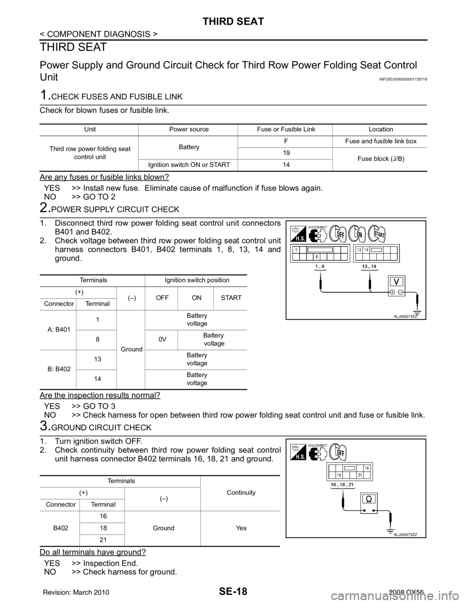
2.POWER SUPPLY CIRCUIT CHECK
1. Disconnect third row power folding seat control unit connectors B401 and B402.
2. Check voltage between third row power folding seat control unit harness connectors B401, B402 terminals 1, 8, 13, 14 and
ground.
Are the inspection results normal?
YES >> GO TO 3
NO >> Check harness for open between third row power folding seat control unit and fuse or fusible link.
3.GROUND CIRCUIT CHECK
1. Turn ignition switch OFF.
2. Check continuity between third row power folding seat control unit harness connector B402 terminals 16, 18, 21 and ground.
Do all terminals have ground?
YES >> Inspection End.
NO >> Check harness for ground.
Unit Power source Fuse or Fusible Link Location
Third row power folding seat control unit Battery
F
Fuse and fusible link box
19 Fuse block (J/B)
Ignition switch ON or START 14
TerminalsIgnition switch position
(+) (–) OFF ON START
Connector Terminal
A: B401 1
Ground Battery
voltage
80 VBattery
voltage
B: B402 13
Battery
voltage
14 Battery
voltage
ALJIA0274ZZ
Te r m i n a l s
Continuity
(+)
(–)
Connector Terminal
B402 16
Ground Yes
18
21
ALJIA0275ZZ
Revision: March 2010 2008 QX56