2008 INFINITI QX56 fuel tank removal
[x] Cancel search: fuel tank removalPage 2111 of 4083
FUEL TANKFL-11
< REMOVAL AND INSTALLATION >
C
DE
F
G H
I
J
K L
M A
FL
NP
O
FUEL TANK
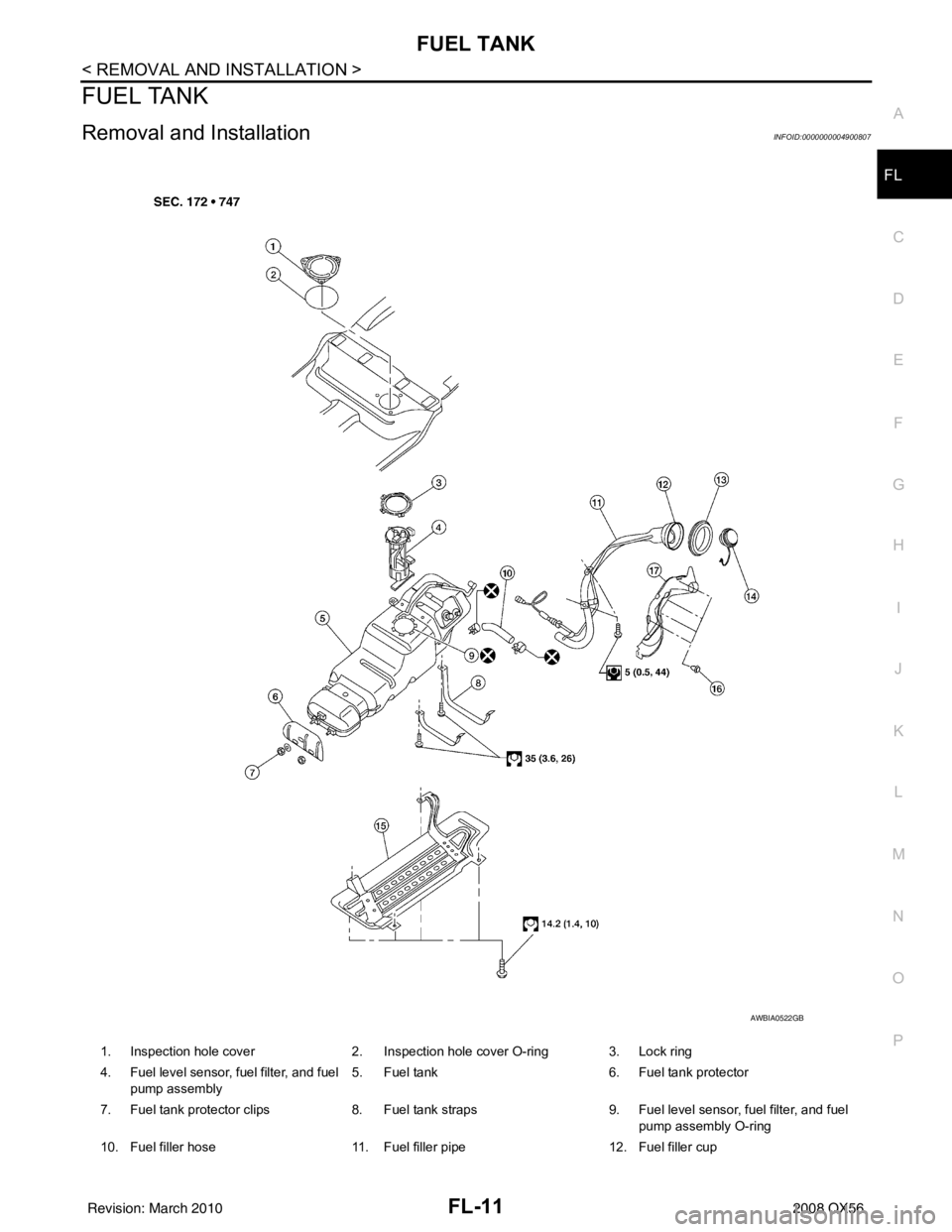
Removal and InstallationINFOID:0000000004900807
1. Inspection hole cover
2. Inspection hole cover O-ring 3. Lock ring
4. Fuel level sensor, fuel filter, and fuel pump assembly 5. Fuel tank
6. Fuel tank protector
7. Fuel tank protector clips 8. Fuel tank straps 9. Fuel level sensor, fuel filter, and fuel
pump assembly O-ring
10. Fuel filler hose 11. Fuel filler pipe 12. Fuel filler cup
AWBIA0522GB
Revision: March 2010 2008 QX56
Page 2112 of 4083
FL-12
< REMOVAL AND INSTALLATION >
FUEL TANK
REMOVAL
WARNING:
Follow the “General Precautions” before working on the fuel system. Refer to FL-4, "
General Precau-
tion" .
1. Drain the fuel from the fuel tank, if necessary. • Position the vehicle so it is level.
2. Remove the fuel filler cap to release the pressure from inside the fuel tank.
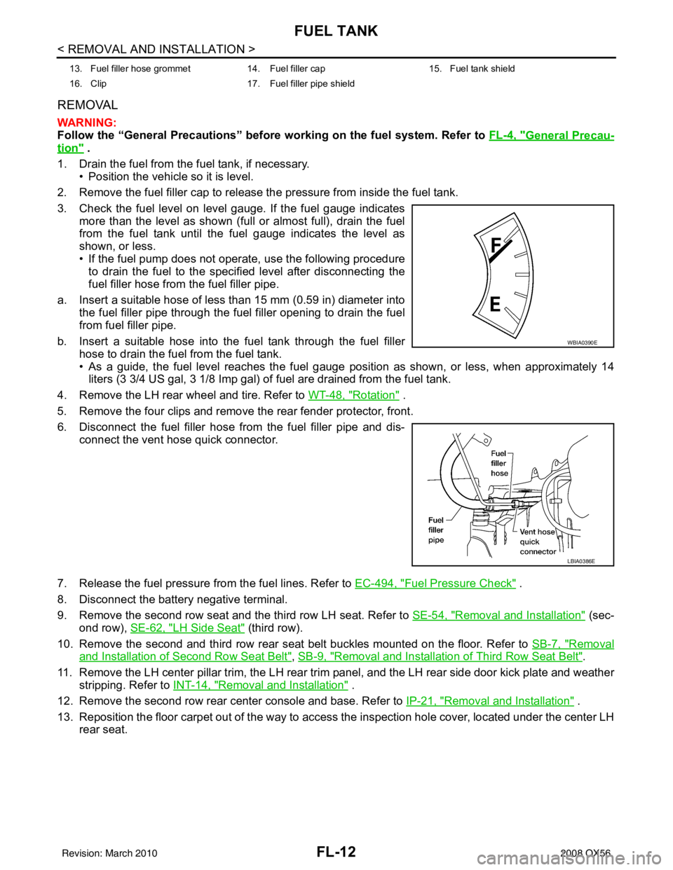
3. Check the fuel level on level gauge. If the fuel gauge indicates more than the level as shown (full or almost full), drain the fuel
from the fuel tank until the fuel gauge indicates the level as
shown, or less.
• If the fuel pump does not operate, use the following procedure
to drain the fuel to the specified level after disconnecting the
fuel filler hose from the fuel filler pipe.
a. Insert a suitable hose of less than 15 mm (0.59 in) diameter into the fuel filler pipe through the fuel filler opening to drain the fuel
from fuel filler pipe.
b. Insert a suitable hose into the fuel tank through the fuel filler hose to drain the fuel from the fuel tank.
• As a guide, the fuel level reaches the fuel gauge position as shown, or less, when approximately 14
liters (3 3/4 US gal, 3 1/8 Imp gal) of fuel are drained from the fuel tank.
4. Remove the LH rear wheel and tire. Refer to WT-48, "
Rotation" .
5. Remove the four clips and remove the rear fender protector, front.
6. Disconnect the fuel filler hose from the fuel filler pipe and dis- connect the vent hose quick connector.
7. Release the fuel pressure from the fuel lines. Refer to EC-494, "
Fuel Pressure Check" .
8. Disconnect the battery negative terminal.
9. Remove the second row seat and the third row LH seat. Refer to SE-54, "
Removal and Installation" (sec-
ond row), SE-62, "
LH Side Seat" (third row).
10. Remove the second and third row rear seat belt buckles mounted on the floor. Refer to SB-7, "
Removal
and Installation of Second Row Seat Belt", SB-9, "Removal and Installation of Third Row Seat Belt".
11. Remove the LH center pillar trim, the LH rear trim panel, and the LH rear side door kick plate and weather
stripping. Refer to INT-14, "
Removal and Installation" .
12. Remove the second row rear center console and base. Refer to IP-21, "
Removal and Installation" .
13. Reposition the floor carpet out of the way to access the inspection hole cover, located under the center LH
rear seat.
13. Fuel filler hose grommet 14. Fuel filler cap 15. Fuel tank shield
16. Clip 17. Fuel filler pipe shield
WBIA0390E
LBIA0386E
Revision: March 2010 2008 QX56
Page 2113 of 4083
FUEL TANKFL-13
< REMOVAL AND INSTALLATION >
C
DE
F
G H
I
J
K L
M A
FL
NP
O
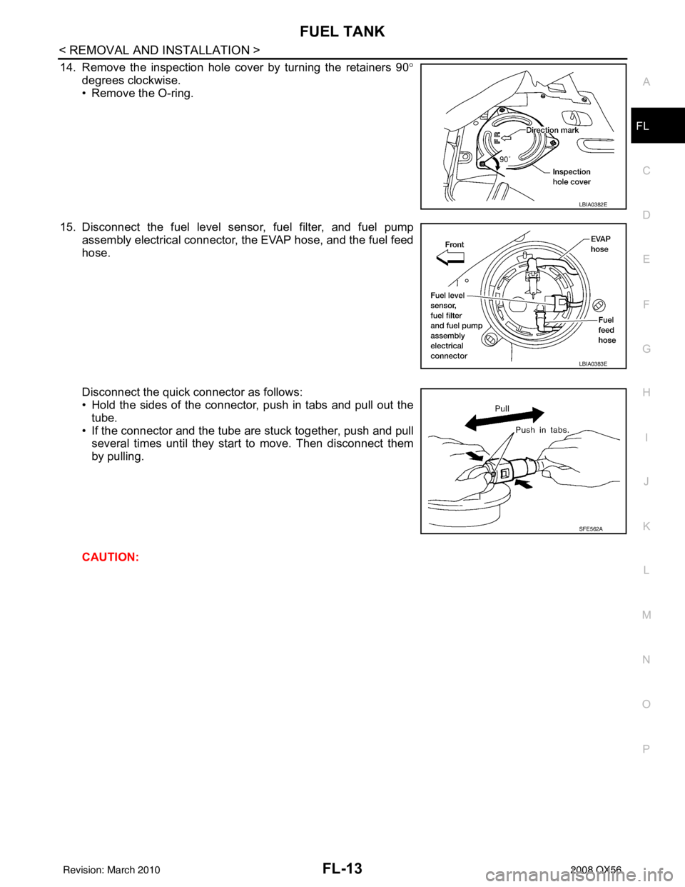
14. Remove the inspection hole cover by turning the retainers 90
°
degrees clockwise.
• Remove the O-ring.
15. Disconnect the fuel level sensor, fuel filter, and fuel pump assembly electrical connector, the EVAP hose, and the fuel feed
hose.
Disconnect the quick connector as follows:
• Hold the sides of the connector, push in tabs and pull out the
tube.
• If the connector and the tube are stuck together, push and pull several times until they start to move. Then disconnect them
by pulling.
CAUTION:
LBIA0382E
LBIA0383E
SFE562A
Revision: March 2010 2008 QX56
Page 2114 of 4083
FL-14
< REMOVAL AND INSTALLATION >
FUEL TANK
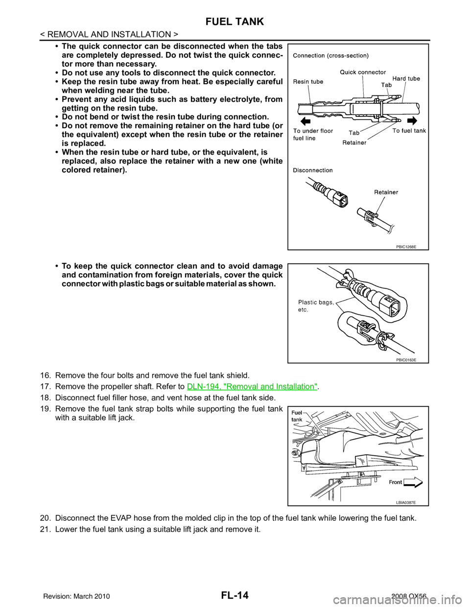
• The quick connector can be disconnected when the tabsare completely depressed. Do not twist the quick connec-
tor more than necessary.
• Do not use any tools to di sconnect the quick connector.
• Keep the resin tube away from heat. Be especially careful
when welding near the tube.
• Prevent any acid liquids such as battery electrolyte, from getting on the resin tube.
• Do not bend or twist the resin tube during connection.
• Do not remove the remaining retainer on the hard tube (or
the equivalent) except when the resin tube or the retainer
is replaced.
• When the resin tube or hard tube, or the equivalent, is
replaced, also replace the retainer with a new one (white
colored retainer).
• To keep the quick connector clean and to avoid damage
and contamination from foreign materials, cover the quick
connector with plastic bags or suit able material as shown.
16. Remove the four bolts and remove the fuel tank shield.
17. Remove the propeller shaft. Refer to DLN-194, "
Removal and Installation".
18. Disconnect fuel filler hose, and vent hose at the fuel tank side.
19. Remove the fuel tank strap bolts while supporting the fuel tank with a suitable lift jack.
20. Disconnect the EVAP hose from the molded clip in the top of the fuel tank while lowering the fuel tank.
21. Lower the fuel tank using a suitable lift jack and remove it.
PBIC1268E
PBIC0163E
LBIA0387E
Revision: March 2010 2008 QX56
Page 2115 of 4083
FUEL TANKFL-15
< REMOVAL AND INSTALLATION >
C
DE
F
G H
I
J
K L
M A
FL
NP
O
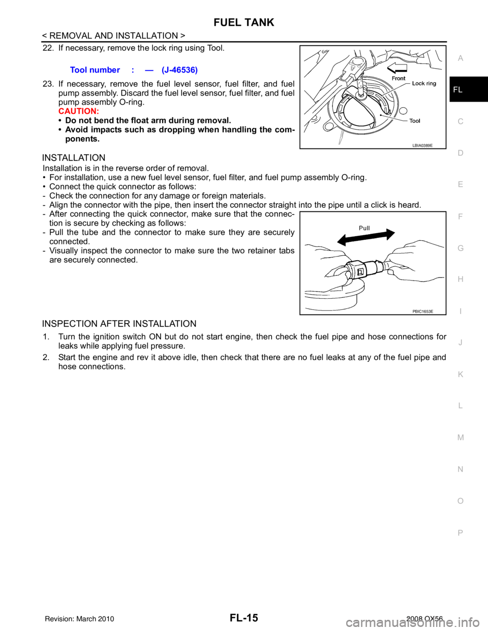
22. If necessary, remove the lock ring using Tool.
23. If necessary, remove the fuel level sensor, fuel filter, and fuel
pump assembly. Discard the fuel level sensor, fuel filter, and fuel
pump assembly O-ring.
CAUTION:
• Do not bend the float arm during removal.
• Avoid impacts such as droppi ng when handling the com-
ponents.
INSTALLATION
Installation is in the reverse order of removal.
• For installation, use a new fuel level sensor, fuel filter, and fuel pump assembly O-ring.
• Connect the quick connector as follows:
- Check the connection for any damage or foreign materials.
- Align the connector with the pipe, t hen insert the connector straight into the pipe until a click is heard.
- After connecting the quick connector, make sure that the connec-
tion is secure by checking as follows:
- Pull the tube and the connector to make sure they are securely connected.
- Visually inspect the connector to make sure the two retainer tabs are securely connected.
INSPECTION AFTER INSTALLATION
1. Turn the ignition switch ON but do not start en gine, then check the fuel pipe and hose connections for
leaks while applying fuel pressure.
2. Start the engine and rev it above idle, then check that there are no fuel leaks at any of the fuel pipe and
hose connections. Tool number : — (J-46536)
LBIA0389E
PBIC1653E
Revision: March 2010
2008 QX56
Page 2169 of 4083
PRECAUTIONSGI-27
< PRECAUTION >
C
DE
F
G H
I
J
K L
M B
GI
N
O P
system. The connectors should be disconnected only when working according to the WORK FLOW of
TROUBLE DIAGNOSES in EC and TM sections.
Three Way CatalystINFOID:0000000001539210
If a large amount of unburned fuel flows into the catalyst, the catalyst temperature will be excessively high. To
prevent this, follow the instructions.
• Use unleaded gasoline only. Leaded gasoline will seriously damage the three way catalyst.
• When checking for ignition spark or measuring engine compression, make tests quickly and only when nec-
essary.
• Do not run engine when the fuel tank level is low, otherwise the engine may misfire, causing damage to the
catalyst.
Do not place the vehicle on flammable material. Keep flammable material off the exhaust pipe and the three
way catalyst.
Precaution for Fuel (Unlead ed Premium Gasoline Recommended)INFOID:0000000006211825
INFINITI recommends the use of unleaded premium gasoline with an octane rating of at least 91 AKI (Anti-
Knock Index) number (Research octane number 96).
If unleaded premium gasoline is not available, unleaded regular gasoline with an octane rating of at least 87
AKI number (Research octane number 91) can be us ed, but only under the following precautions:
• have the fuel tank filled only partially with unleaded regular gasoline, and fill up with unleaded premium gas- oline as soon as possible.
• avoid full throttle driving and abrupt acceleration.
However, for maximum vehicle performance, the u se of unleaded premium gasoline is recommended.
CAUTION:
Do not use leaded gasoline. Usin g leaded gasoline will damage the three way catalyst. Using a fuel
other than that specified could adversely affect the emission cont rol devices and systems, and could
also affect the warranty coverage validity.
Multiport Fuel Inje ction System or Engine Control SystemINFOID:0000000001539213
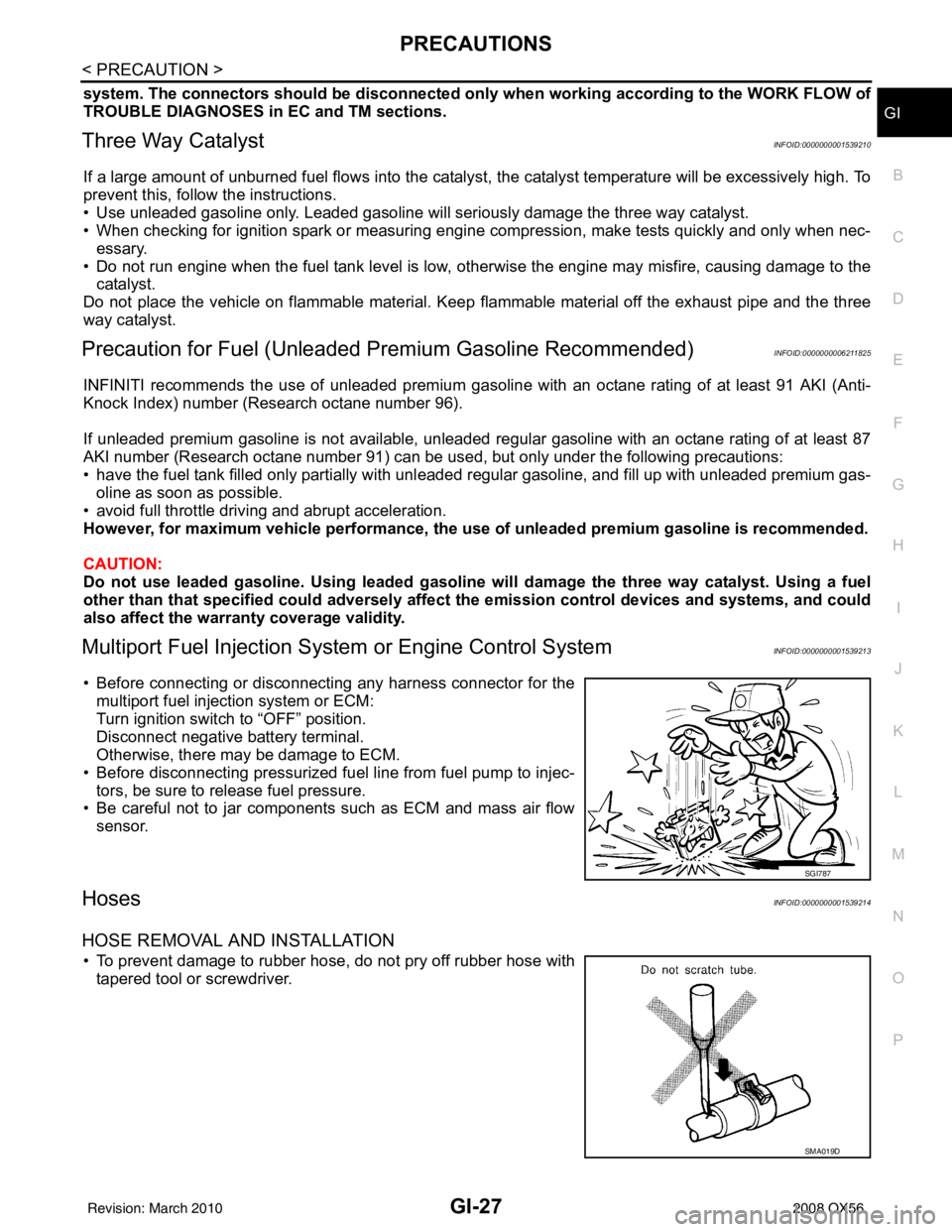
• Before connecting or disconnecting any harness connector for the
multiport fuel injection system or ECM:
Turn ignition switch to “OFF” position.
Disconnect negative battery terminal.
Otherwise, there may be damage to ECM.
• Before disconnecting pressurized fuel line from fuel pump to injec- tors, be sure to release fuel pressure.
• Be careful not to jar components such as ECM and mass air flow
sensor.
HosesINFOID:0000000001539214
HOSE REMOVAL AND INSTALLATION
• To prevent damage to rubber hose, do not pry off rubber hose withtapered tool or screwdriver.
SGI787
SMA019D
Revision: March 2010 2008 QX56
Page 2615 of 4083
ENGINE MAINTENANCEMA-17
< ON-VEHICLE MAINTENANCE >
C
DE
F
G H
I
J
K L
M B
MA
N
O A
2. Fill the radiator and the reservoir tank (to the “MAX”
line), with water. Reinstall the radiator cap and leave
the vented reservoir cap off.
3. Run the engine until it reaches normal operating temperature.
4. Press the engine accelerator two or three times under no-load.
5. Stop the engine and wait until it cools down.
6. Drain the water from the engine cooling system. Refer to CO-11, "
Changing Engine Coolant" .
7. Repeat steps 2 through 6 until clear water begins to drain from the radiator.
Checking Fuel LineINFOID:0000000001606172
Inspect the fuel lines and fuel tank for improper mounting, leaks,
cracks, damage, loose connections, chafing, or deterioration.
As necessary, repair or replace any faulty parts.
Changing Fuel FilterINFOID:0000000001606173
The fuel filter is part of the fuel level sensor unit, fuel filter and fuel pump assembly. Refer to FL-7, "Removal
and Installation" .
WARNING:
Before replacing the fuel filter, release the fuel pressure from the fuel system. Refer to EC-494, "
Fuel
Pressure Check".
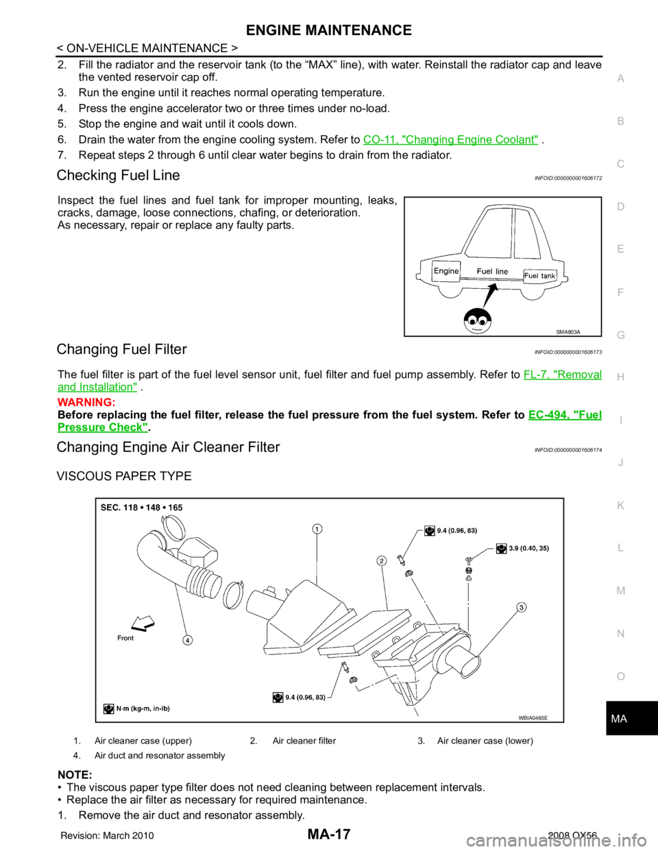
Changing Engine Air Cleaner FilterINFOID:0000000001606174
VISCOUS PAPER TYPE
NOTE:
• The viscous paper type filter does not need cleaning between replacement intervals.
• Replace the air filter as necessary for required maintenance.
1. Remove the air duct and resonator assembly.
SMA803A
1. Air cleaner case (upper) 2. Air cleaner filter3. Air cleaner case (lower)
4. Air duct and resonator assembly
WBIA0465E
Revision: March 2010 2008 QX56
Page 2619 of 4083
ENGINE MAINTENANCEMA-21
< ON-VEHICLE MAINTENANCE >
C
DE
F
G H
I
J
K L
M B
MA
N
O A
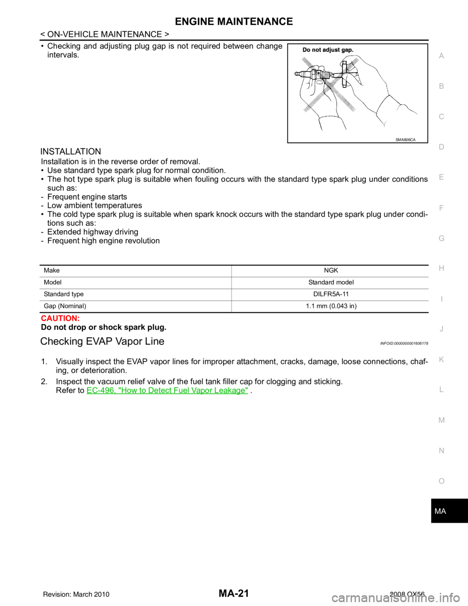
• Checking and adjusting plug gap is not required between change
intervals.
INSTALLATION
Installation is in the reverse order of removal.
• Use standard type spark plug for normal condition.
• The hot type spark plug is suitable when fouling occurs with the standard type spark plug under conditionssuch as:
- Frequent engine starts
- Low ambient temperatures
• The cold type spark plug is suitable when spark knock occurs with the standard type spark plug under condi- tions such as:
- Extended highway driving
- Frequent high engine revolution
CAUTION:
Do not drop or shock spark plug.
Checking EVAP Vapor LineINFOID:0000000001606178
1. Visually inspect the EVAP vapor lines for improper attachment, cracks, damage, loose connections, chaf-
ing, or deterioration.
2. Inspect the vacuum relief valve of the fuel tank filler cap for clogging and sticking.
Refer to EC-496, "
How to Detect Fuel Vapor Leakage" .
SMA806CA
Make NGK
Model Standard model
Standard type DILFR5A-11
Gap (Nominal) 1.1 mm (0.043 in)
Revision: March 2010 2008 QX56