Page 2443 of 4083
INL-60
< ON-VEHICLE REPAIR >
INTERIOR ROOM LAMP
1. Disconnect the negative battery terminal.
2. Using a suitable tool (A), release the tabs and remove the vanitymirror lamp lens (1).
3. Release one side of the bulb (2) from the tab, then pull straight out to remove.
CAUTION:
Wrap a cloth around tool to protect the housing and lens.
GLOVE BOX LAMP
Removal
1. Remove instrument lower panel RH and glove box. Refer to IP-17, "Removal and Installation".
2. Rotate glove box lamp socket and rotate counterclockwise to release from steering member.
Installation
Installation is in the reverse order of removal.
Bulb Replacement
1. Disconnect the negative battery terminal.
2. Remove instrument lower panel RH and glove box. Refer to IP-17, "
Removal and Installation".
3. Pull bulb (2) straight out from glove box lamp socket (1) to remove.
STEP LAMP
Removal
Vanity mirror lamp bulb : 12V - 1.8W
ALLIA0320ZZ
Glove box lamp bulb : 12V - 3.4W
ALLIA0321ZZ
Revision: March 2010 2008 QX56
Page 2444 of 4083
INTERIOR ROOM LAMPINL-61
< ON-VEHICLE REPAIR >
C
DE
F
G H
I
J
K
M A
B
INL
N
O P
1. Disconnect the negative battery terminal.
2. Insert a suitable tool between door finisher and step lamp lens/socket to release the pawls.
3. Disconnect the step lamp connector, then remove step lamp.
Installation
Installation is in the reverse order of removal.
Bulb Replacement
1. Disconnect the negative battery cable.
2. Remove the step lamp lens/socket.
3. Pull the bulb straight out to remove.
PERSONAL LAMP
Removal
1. Disconnect the negative battery terminal.
ALLIA0013ZZ
1. Step lamp connector 2. Door finisher3. Step lamp lens/socket
4. Step lamp bulb Vehicle front
Step lamp bulb : 12V - 3.8W
Revision: March 2010 2008 QX56
Page 2445 of 4083
INL-62
< ON-VEHICLE REPAIR >
INTERIOR ROOM LAMP
2. Remove overhead console. Refer to INT-17, "Removal and
Installation".
3. Remove personal lamp screws (3).
4. Disconnect personal lamp electrical connectors (1), then remove personal lamps (2) from overhead console.
Installation
Installation is in the reverse order of removal.
Bulb Replacement
1. Disconnect the negative battery terminal.
2. Using a suitable tool (A), release the pawls and remove per-sonal lamp lens (1).
3. Pull bulb (2) straight out to remove.
CAUTION:
Wrap a cloth around tool to protect the housing and lens.
FOOTWELL LAMP
Removal
1. Disconnect the negative battery terminal.
2. Rotate footwell lamp socket (3) counterclockwise from bracket.
Installation
Installation is in the reverse order of removal.
Bulb Replacement
ALLIA0322ZZ
Personal lamp bulb : 12V - 6W
ALLIA0323ZZ
ALLIA0324ZZ
Revision: March 2010 2008 QX56
Page 2447 of 4083
INL-64
< ON-VEHICLE REPAIR >
ILLUMINATION
ILLUMINATION
Removal and InstallationINFOID:0000000001534339
ILLUMINATION CONTROL SWITCH
Removal
The illumination control switch, is replaced as a part of the combination meter assembly. Refer to MWI-76,
"Removal and Installation".
Installation
Installation is in the reverse order of removal.
CARGO LAMP
Removal
1. Disconnect the negative battery terminal.
2. Using a suitable tool (A), release the pawls and remove the
cargo lamp lens (1).
3. Remove cargo lamp screws (2).
4. Disconnect the connector, then remove cargo lamp.
Installation
Installation is in the reverse order of removal.
Bulb Replacement
1. Disconnect the negative battery terminal.
2. Using a suitable tool, release the pawls and remove the cargo lamp lens.
3. Release the cargo lamp bulb retainers (1), then pull bulb (2) straight out to remove.
CONSOLE ILLUMINATION LAMP
Removal
ALLIA0325ZZ
Cargo lamp bulb : 12V - 8W
ALLIA0326ZZ
Revision: March 2010 2008 QX56
Page 2448 of 4083
ILLUMINATIONINL-65
< ON-VEHICLE REPAIR >
C
DE
F
G H
I
J
K
M A
B
INL
N
O P
The console illumination lamp (1) is replaced as part of the map
lamp assembly (2). Refer to INT-17, "
Removal and Installation".
⇐ : Vehicle front
Installation
Installation is in the reverse order of removal.
Bulb Replacement
1. Disconnect the negative battery terminal.
2. Remove overhead console. Refer to INT-17, "
Removal and Installation".
3. Rotate console illumination lamp bulb (1) counterclockwise, then pull straight out away from map lamp assembly (2) to remove.
ALLIA0328ZZ
ALLIA0327ZZ
Revision: March 2010 2008 QX56
Page 3386 of 4083

SR-10
< ON-VEHICLE REPAIR >
FRONT PASSENGER AIR BAG MODULE
FRONT PASSENGER AIR BAG MODULE
Removal and InstallationINFOID:0000000001602203
The passenger air bag module originally installed in the vehicle uses direct-connect style harness connectors.
Service replacement passenger air bag modules use tab-locking style harness connectors. If the passenger
air bag module is replaced or if the direct-connect harness connectors are damaged, the vehicle wiring har-
ness must be modified to allow connection of the se rvice replacement passenger air bag module. Refer to
"Service Replacement Passenger Air Bag Module" within the INSTALLATION procedure in this section for wir-
ing harness modifiation procedure.
REMOVAL
CAUTION:
• Do not attempt to repair or replace damaged di rect-connect front passenger air bag module connec-
tors. If a direct-connect harness connector is damaged, the front passenger air bag must be
replaced and the wiri ng harness modified.
• Before servicing SRS, turn the ignition switch off, disco nnect both battery cables and wait at least
three minutes.
• Always work from the side of or under front passenger air bag module.
1. Remove the glove box. Refer to IP-17, "
Exploded View".
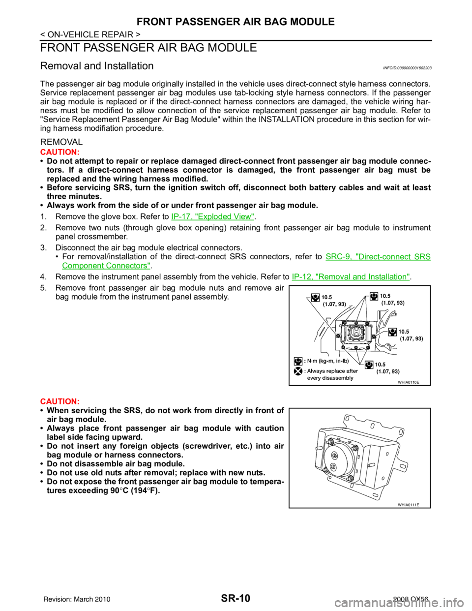
2. Remove two nuts (through glove box opening) retaining front passenger air bag module to instrument panel crossmember.
3. Disconnect the air bag module electrical connectors. • For removal/installation of the direct-connect SRS connectors, refer to SRC-9, "
Direct-connect SRS
Component Connectors".
4. Remove the instrument panel assembly from the vehicle. Refer to IP-12, "
Removal and Installation".
5. Remove front passenger air bag module nuts and remove air bag module from the instrument panel assembly.
CAUTION:
• When servicing the SRS, do not work from directly in front of
air bag module.
• Always place front passenger air bag module with caution label side facing upward.
• Do not insert any foreign object s (screwdriver, etc.) into air
bag module or harness connectors.
• Do not disassemble air bag module.
• Do not use old nuts after removal; replace with new nuts.
• Do not expose the front passenger air bag module to tempera- tures exceeding 90 °C (194 °F).
WHIA0110E
WHIA0111E
Revision: March 2010 2008 QX56
Page 3387 of 4083

FRONT PASSENGER AIR BAG MODULESR-11
< ON-VEHICLE REPAIR >
C
DE
F
G
I
J
K L
M A
B
SR
N
O P
• Replace the air bag module if it has been dropped or sus-
tained an impact.
• Do not allow oil, grease or water to come in contact with the
air bag module.
• For removal/installation of the direct-connect SRS connec- tors, refer to SRC-9, "
Direct-connect SRS Component Con-
nectors".
INSTALLATION
Original Passenger Air Bag Module
Installation is in the reverse order of removal.
• For removal and installation of the direct-connect SRS connectors, refer to SRC-9, "
Direct-connect SRS
Component Connectors".
CAUTION:
• Always work from the side of or under front passenger air bag module.
• After the work is completed, perform self-diagnosi s to check that no malfunction is detected. Refer
to SRC-13, "
SRS Operation Check".
Service Replacement Passenger Air Bag Module
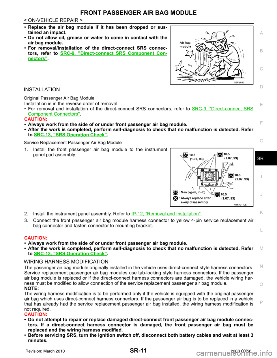
1. Install the front passenger air bag module to the instrument
panel pad assembly.
2. Install the instrument panel assembly. Refer to IP-12, "
Removal and Installation".
3. Connect the front passenger air bag module harness connector to yellow 4-pin service replacement air bag connector and fasten connector to mounting bracket.
CAUTION:
• Always work from the side of or under front passenger air bag module.
• After the work is completed, perform self-diagnosi s to check that no malfunction is detected. Refer
to SRC-13, "
SRS Operation Check".
WIRING HARNESS MODIFICATION
The passenger air bag module originally installed in t he vehicle uses direct-connect style harness connectors.
Service replacement passenger air bag modules use t ab-locking style harness connectors. If the passenger
air bag module is replaced or if the direct-connect harness connectors are damaged, the vehicle wiring har-
ness must be modified to allow connection of t he service replacement passenger air bag module.
NOTE:
The wiring harness modification is to be performed only if the vehicle is equipped with the original passenger
air bag which uses direct-connect harness connectors. If the passenger air bag is to be replaced in a vehicle
that has already had the service replacement passenger air bag installed, the wiring harness modification is
not required.
CAUTION:
• Do not attempt to repair or replace damaged dir ect-connect front passenger air bag module connec-
tors. If a direct-connect harness connector is damaged, the front passenger air bag must be
replaced and the wiri ng harness modified.
• Before servicing SRS, turn the igni tion switch off, disconnect both battery cables and wait at least 3
minutes.
SBF814E
WHIA0110E
Revision: March 2010 2008 QX56
Page 3389 of 4083

SIDE CURTAIN AIR BAG MODULESR-13
< ON-VEHICLE REPAIR >
C
DE
F
G
I
J
K L
M A
B
SR
N
O P
SIDE CURTAIN AIR BAG MODULE
Removal and InstallationINFOID:0000000001602204
REMOVAL
CAUTION:
• Do not attempt to repair or replace damaged direct-connect SRS component connectors. If a direct- connect harness connector is damage d, the harness must be replaced.
• Before servicing the SRS, turn the ignition switch off, disconnect both battery cables and wait at least 3 minutes.
• When servicing the SRS, do not work from directly in front of air bag module.
• Do not insert any foreign objects (screwdriver, etc.) into air bag module or harness connectors.
• Do not disassemble air bag module.
• Do not expose the air bag modu le to temperatures exceeding 90°C (194 °F).
• Replace side curtain air bag modu le if it has been dropped or
sustained an impact.
• Do not allow oil, grease or water to come in contact with the
air bag module.
1. Remove headlining. Refer to INT-17, "
Removal and Installation".
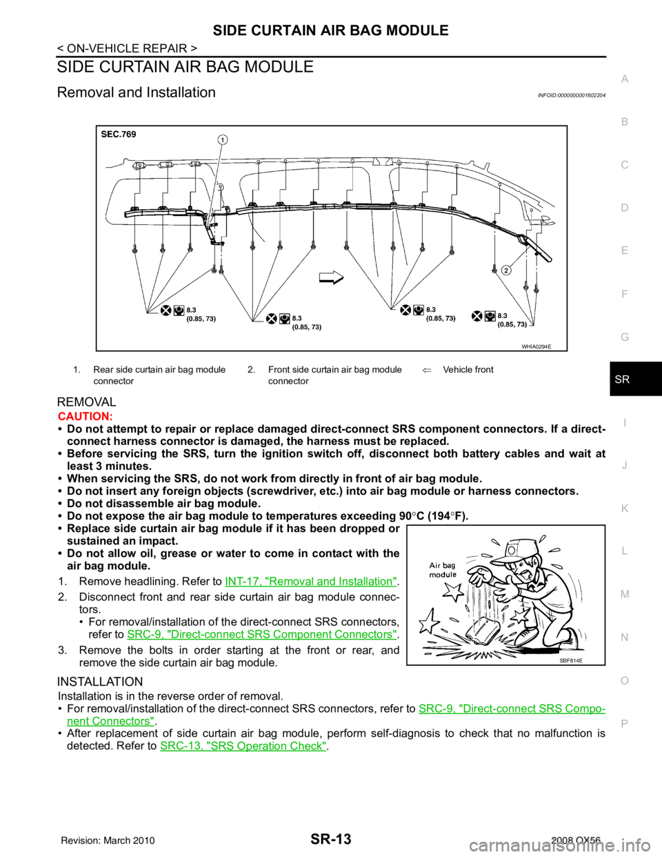
2. Disconnect front and rear side curtain air bag module connec- tors.
• For removal/installation of the direct-connect SRS connectors,refer to SRC-9, "
Direct-connect SRS Component Connectors".
3. Remove the bolts in order starting at the front or rear, and remove the side curtain air bag module.
INSTALLATION
Installation is in the reverse order of removal.
• For removal/installation of the direct-connect SRS connectors, refer to SRC-9, "
Direct-connect SRS Compo-
nent Connectors".
• After replacement of side curtain air bag module, per form self-diagnosis to check that no malfunction is
detected. Refer to SRC-13, "
SRS Operation Check".
1. Rear side curtain air bag module
connector 2. Front side curtain air bag module
connector ⇐
Vehicle front
WHIA0294E
SBF814E
Revision: March 2010 2008 QX56