2008 INFINITI QX56 ECU
[x] Cancel search: ECUPage 3940 of 4083

WCS
BCM (BODY CONTROL MODULE)WCS-63
< ECU DIAGNOSIS >
C
DE
F
G H
I
J
K L
M B A
O P
DTC Inspection Priority ChartINFOID:0000000004871177
If some DTCs are displayed at the same time, perform inspections one by one based on the following priority
chart.
DTC IndexINFOID:0000000004871178
NOTE: Details of time display
• CRNT: Displays when there is a malfunction now or after returning to the normal condition until turning igni-
tion switch OFF → ON again.
• 1 - 39: Displayed if any previous ma lfunction is present when current conditi on is normal. It increases like 1
→ 2 → 3...38 → 39 after returning to the normal condition whenever ignition switch OFF → ON. The counter
remains at 39 even if the number of cycles exceeds it. It is counted from 1 again when turning ignition switch
OFF → ON after returning to the normal condi tion if the malfunction is detected again.
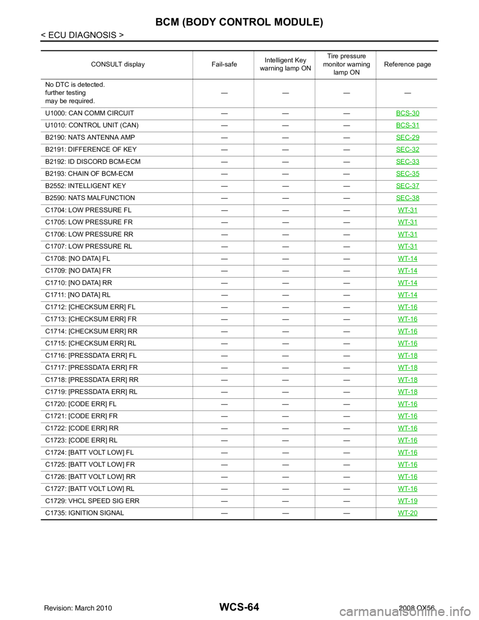
Display contents of CONSULT Fail-safe Cancellation
U1000: CAN COMM CIRCUIT I nhibit engine crankingWhen the BCM re-establishes communication with the other mod-
ules.
U1010: CONTROL UNIT (CAN) Inhibit engine cranking When the BCM re-start communicating with the other modules.
Priority DTC
1 • U1000: CAN COMM CIRCUIT
• U1010: CONTROL UNIT (CAN)
2 • B2190: NATS ANTENNA AMP
• B2191: DIFFERENCE OF KEY
• B2192: ID DISCORD BCM-ECM
• B2193: CHAIN OF BCM-ECM
• B2013: STRG COMM 1
• B2552: INTELLIGENT KEY
• B2590: NATS MALFUNCTION
3 • C1729: VHCL SPEED SIG ERR
• C1735: IGNITION SIGNAL
4 • C1704: LOW PRESSURE FL
• C1705: LOW PRESSURE FR
• C1706: LOW PRESSURE RR
• C1707: LOW PRESSURE RL
• C1708: [NO DATA] FL
• C1709: [NO DATA] FR
• C1710: [NO DATA] RR
• C1711: [NO DATA] RL
• C1712: [CHECKSUM ERR] FL
• C1713: [CHECKSUM ERR] FR
• C1714: [CHECKSUM ERR] RR
• C1715: [CHECKSUM ERR] RL
• C1716: [PRESSDATA ERR] FL
• C1717: [PRESSDATA ERR] FR
• C1718: [PRESSDATA ERR] RR
• C1719: [PRESSDATA ERR] RL
• C1720: [CODE ERR] FL
• C1721: [CODE ERR] FR
• C1722: [CODE ERR] RR
• C1723: [CODE ERR] RL
• C1724: [BATT VOLT LOW] FL
• C1725: [BATT VOLT LOW] FR
• C1726: [BATT VOLT LOW] RR
• C1727: [BATT VOLT LOW] RL
Revision: March 2010
2008 QX56
Page 3941 of 4083

WCS-64
< ECU DIAGNOSIS >
BCM (BODY CONTROL MODULE)
CONSULT displayFail-safeIntelligent Key
warning lamp ON Tire pressure
monitor warning lamp ON Reference page
No DTC is detected.
further testing
may be required. ————
U1000: CAN COMM CIRCUIT ———BCS-30
U1010: CONTROL UNIT (CAN) ———BCS-31
B2190: NATS ANTENNA AMP ———SEC-29
B2191: DIFFERENCE OF KEY ———SEC-32
B2192: ID DISCORD BCM-ECM ———SEC-33
B2193: CHAIN OF BCM-ECM ———SEC-35
B2552: INTELLIGENT KEY ———SEC-37
B2590: NATS MALFUNCTION ———SEC-38
C1704: LOW PRESSURE FL ———WT-31
C1705: LOW PRESSURE FR ———WT-31
C1706: LOW PRESSURE RR ———WT-31
C1707: LOW PRESSURE RL ———WT-31
C1708: [NO DATA] FL ———WT-14
C1709: [NO DATA] FR ———WT-14
C1710: [NO DATA] RR ———WT-14
C1711: [NO DATA] RL ———WT-14
C1712: [CHECKSUM ERR] FL ———WT-16
C1713: [CHECKSUM ERR] FR ———WT-16
C1714: [CHECKSUM ERR] RR ———WT-16
C1715: [CHECKSUM ERR] RL ———WT-16
C1716: [PRESSDATA ERR] FL ———WT-18
C1717: [PRESSDATA ERR] FR ———WT-18
C1718: [PRESSDATA ERR] RR ———WT-18
C1719: [PRESSDATA ERR] RL ———WT-18
C1720: [CODE ERR] FL ———WT-16
C1721: [CODE ERR] FR ———WT-16
C1722: [CODE ERR] RR ———WT-16
C1723: [CODE ERR] RL ———WT-16
C1724: [BATT VOLT LOW] FL ———WT-16
C1725: [BATT VOLT LOW] FR ———WT-16
C1726: [BATT VOLT LOW] RR ———WT-16
C1727: [BATT VOLT LOW] RL ———WT-16
C1729: VHCL SPEED SIG ERR ———WT-19
C1735: IGNITION SIGNAL ———WT-20
Revision: March 2010 2008 QX56
Page 3947 of 4083

WT-1
SUSPENSION
C
DF
G H
I
J
K L
M
SECTION WT
A
B
WT
N
O PCONTENTS
ROAD WHEELS & TIRES
BASIC INSPECTION ....... .............................3
DIAGNOSIS AND REPAIR WORKFLOW ..... .....3
Repair Work Flow ................................................ ......3
INSPECTION AND ADJUSTMENT .....................5
Preliminary Check ............................................... ......5
Transmitter Wake Up Operation ...............................5
ID Registration Procedure .........................................6
FUNCTION DIAGNOSIS ...............................8
TPMS .............................................................. .....8
System Diagram .................................................. ......8
System Description ...................................................8
System Component .................................................10
DIAGNOSIS SYSTEM (BCM) ............................11
CONSULT-III Function (BCM) ............................. ....11
Self-Diagnosis (Without CONSULT-III) ...................12
COMPONENT DIAGNOSIS .........................14
C1708 - C1711 DATA FROM TRANSMITTER
NOT BEING RECEIVED ................................. ....
14
Description .......................................................... ....14
DTC Logic ...............................................................14
Diagnosis Procedure ...............................................14
Special Repair Requirement ...................................15
C1712 - C1715, C1720 - C1723, C1724 -
C1727 TRANSMITTER MALFUNCTION ....... ....
16
Description .......................................................... ....16
DTC Logic ...............................................................16
Diagnosis Procedure ...............................................16
Special Repair Requirement ...................................17
C1716 - C1719 TRANSMITTER PRESSURE
MALFUNCTION .............................................. ....
18
Description .......................................................... ....18
DTC Logic ...............................................................18
Diagnosis Procedure ...............................................18
Special Repair Requirement ................................ ....18
C1729 VEHICLE SPEED SIGNAL ....................19
Description ...............................................................19
DTC Logic ................................................................19
Diagnosis Procedure ...............................................19
Special Repair Requirement ....................................19
C1735 IGNITION SIGNAL .................................20
Description ...............................................................20
DTC Logic ................................................................20
Diagnosis Procedure ...............................................20
Special Repair Requirement ....................................20
ECU DIAGNOSIS .........................................21
BCM (BODY CONTROL MODULE) .................21
Reference Value .................................................. ....21
Terminal Layout .......................................................23
Physical Values ................................................... ....23
Wiring Diagram ........................................................29
Self-Diagnosis (With CONSULT-III) ........................31
Self-Diagnosis (Without CONSULT-III) ...................32
SYMPTOM DIAGNOSIS ..............................34
TPMS .................................................................34
Symptom Table ................................................... ....34
LOW TIRE PRESSURE WARNING LAMP
DOES NOT TURN ON .......................................
35
Low Tire Pressure Warning Lamp Does Not Come
On When Ignition Switch Is Turned On ...................
35
LOW TIRE PRESSURE WARNING LAMP
STAYS ON ........................................................
36
Low Tire Pressure Warning Lamp Stays On When
Ignition Switch Is Turned On ............................... ....
36
LOW TIRE PRESSURE WARNING LAMP
BLINKS .............................................................
37
Revision: March 2010 2008 QX56
Page 3957 of 4083

DIAGNOSIS SYSTEM (BCM)WT-11
< FUNCTION DIAGNOSIS >
C
DF
G H
I
J
K L
M A
B
WT
N
O P
DIAGNOSIS SYSTEM (BCM)
CONSULT-III Function (BCM)INFOID:0000000001735378
CONSULT-III DIAGNOSTIC MODES
CONSULT-III can display each diagnostic item using the diagnostic test modes shown following.
DESCRIPTION
During driving, the tire pressure monitoring system receives the signal transmitted from the transmitter
installed in each wheel, and turns on the low tire pressure warning lamp when the tire pressure becomes low.
The control unit (BCM) for this system has pr essure judgement and self-diagnosis functions.
FUNCTION
When the tire pressure monitoring system detects low infl ation pressure or an internal malfunction, the low tire
pressure warning lamp in the combination meter comes on. The malfunction is indicated by the low tire pres-
sure warning lamp flashing.
CONSULT-III Application to Ti re Pressure Monitoring System
× : Applicable
– : Not applicable
Data Monitor Mode
Diagnostic mode Description
WORK SUPPORT Supports inspections and adjustments. Commands are transmitted to the BCM
for setting the status suitable for required operation, input/output signals are re-
ceived from the BCM and received data is displayed.
DATA MONITOR Displays BCM input/output data in real time.
ACTIVE TEST Operation of electrical loads can be checked by sending drive signal to them.
SELF-DIAG RESULTS Displays BCM self-diagnosis results.
CAN DIAG SUPPORT MNTR The result of transmit/receive diagnosis of CAN communication can be read.
ECU PART NUMBER BCM part number can be read.
CONFIGURATION Performs BCM configuration read/write functions.
ITEMSELF-DIAGNOSTIC RESULTS DATA MONITOR
Front - Left transmitter ××
Front - Right transmitter ××
Rear - Left transmitter ××
Rear - Right transmitter ××
Warning lamp —×
Vehicle speed ××
CAN Communication ××
MONITORCONDITION SPECIFICATION
VHCL SPEED Drive vehicle. Vehicle speed (km/h or MPH)
AIR PRESS FL
AIR PRESS FR
AIR PRESS RR
AIR PRESS RL • Drive vehicle for a few minutes.
Tire pressure (kPa or psi)
or
• Ignition switch ON and activation tool is transmitting activation signals.
Revision: March 2010 2008 QX56
Page 3967 of 4083

BCM (BODY CONTROL MODULE)WT-21
< ECU DIAGNOSIS >
C
DF
G H
I
J
K L
M A
B
WT
N
O P
ECU DIAGNOSIS
BCM (BODY CONTROL MODULE)
Reference ValueINFOID:0000000004291536
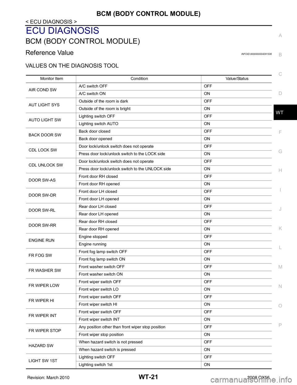
VALUES ON THE DIAGNOSIS TOOL
Monitor Item Condition Value/Status
AIR COND SW A/C switch OFF
OFF
A/C switch ON ON
AUT LIGHT SYS Outside of the room is dark
OFF
Outside of the room is bright ON
AUTO LIGHT SW Lighting switch OFF
OFF
Lighting switch AUTO ON
BACK DOOR SW Back door closed
OFF
Back door opened ON
CDL LOCK SW Door lock/unlock switch does not operate
OFF
Press door lock/unlock switch to the LOCK side ON
CDL UNLOCK SW Door lock/unlock switch does not operate
OFF
Press door lock/unlock switch to the UNLOCK side ON
DOOR SW-AS Front door RH closed
OFF
Front door RH opened ON
DOOR SW-DR Front door LH closed
OFF
Front door LH opened ON
DOOR SW-RL Rear door LH closed
OFF
Rear door LH opened ON
DOOR SW-RR Rear door RH closed
OFF
Rear door RH opened ON
ENGINE RUN Engine stopped
OFF
Engine running ON
FR FOG SW Front fog lamp switch OFF
OFF
Front fog lamp switch ON ON
FR WASHER SW Front washer switch OFF
OFF
Front washer switch ON ON
FR WIPER LOW Front wiper switch OFF
OFF
Front wiper switch LO ON
FR WIPER HI Front wiper switch OFF
OFF
Front wiper switch HI ON
FR WIPER INT Front wiper switch OFF
OFF
Front wiper switch INT ON
FR WIPER STOP Any position other than front wiper stop position
OFF
Front wiper stop position ON
HAZARD SW When hazard switch is not pressed
OFF
When hazard switch is pressed ON
LIGHT SW 1ST Lighting switch OFF
OFF
Lighting switch 1st ON
Revision: March 2010 2008 QX56
Page 3968 of 4083

WT-22
< ECU DIAGNOSIS >
BCM (BODY CONTROL MODULE)
HEADLAMP SW1Headlamp switch OFF OFF
Headlamp switch 1st
ON
HEADLAMP SW2 Headlamp switch OFF
OFF
Headlamp switch 1st ON
HI BEAM SW High beam switch OFF
OFF
High beam switch HI ON
IGN ON SW Ignition switch OFF or ACC
OFF
Ignition switch ON ON
IGN SW CAN Ignition switch OFF or ACC
OFF
Ignition switch ON ON
INT VOLUME Wiper intermittent dial is in a dial position 1 - 7 1 - 7
I-KEY LOCK LOCK button of Intelligent Key is not pressed
OFF
LOCK button of Intelligent Key is pressed ON
I-KEY UNLOCK UNLOCK button of Intelligent Key is not pressed
OFF
UNLOCK button of Intelligent Key is pressed ON
KEY ON SW Mechanical key is removed from key cylinder
OFF
Mechanical key is inserted to key cylinder ON
OIL PRESS SW • Ignition switch OFF or ACC
• Engine running
OFF
Ignition switch ON ON
PASSING SW Other than lighting switch PASS
OFF
Lighting switch PASS ON
REAR DEF SW Rear window defogger switch OFF
OFF
Rear window defogger switch ON ON
RR WASHER SW Rear washer switch OFF
OFF
Rear washer switch ON ON
RR WIPER INT Rear wiper switch OFF
OFF
Rear wiper switch INT ON
RR WIPER ON Rear wiper switch OFF
OFF
Rear wiper switch ON ON
RR WIPER STOP Rear wiper stop position
OFF
Other than rear wiper stop position ON
TAIL LAMP SW Lighting switch OFF
OFF
Lighting switch 1ST ON
TRNK OPNR SW When back door opener switch is not pressed
OFF
When back door opener switch is pressed ON
TURN SIGNAL L Turn signal switch OFF
OFF
Turn signal switch LH ON
TURN SIGNAL R Turn signal switch OFF
OFF
Turn signal switch RH ON
VEHICLE SPEED While driving Equivalent to speedometer reading
Monitor Item
Condition Value/Status
Revision: March 2010 2008 QX56
Page 3969 of 4083

BCM (BODY CONTROL MODULE)WT-23
< ECU DIAGNOSIS >
C
DF
G H
I
J
K L
M A
B
WT
N
O P
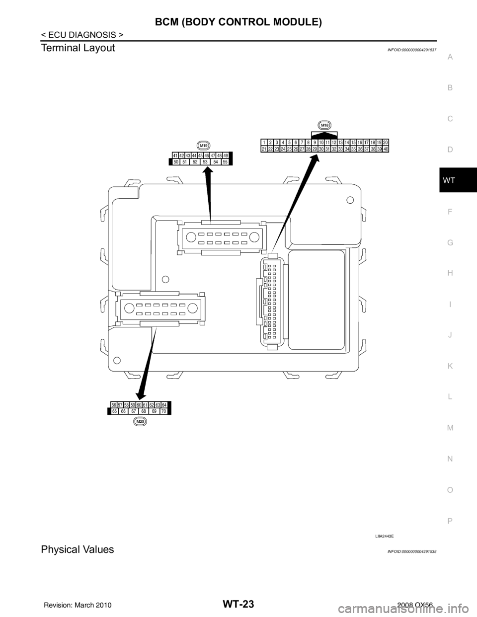
Terminal LayoutINFOID:0000000004291537
Physical ValuesINFOID:0000000004291538
LIIA2443E
Revision: March 2010 2008 QX56
Page 3970 of 4083

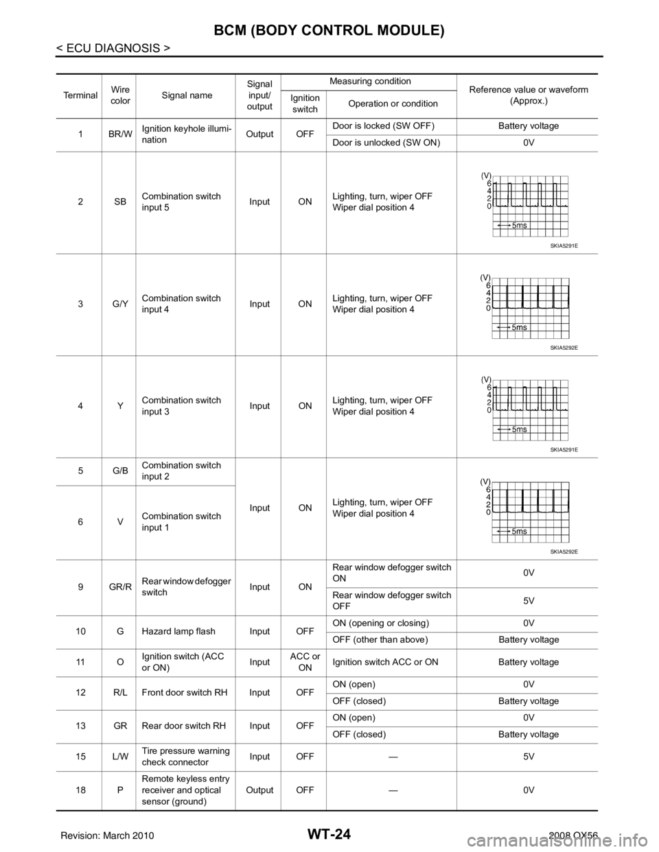
WT-24
< ECU DIAGNOSIS >
BCM (BODY CONTROL MODULE)
Te r m i n a lWire
color Signal name Signal
input/
output Measuring condition
Reference value or waveform
(Approx.)
Ignition
switch Operation or condition
1BR/W Ignition keyhole illumi-
nation Output OFFDoor is locked (SW OFF)
Battery voltage
Door is unlocked (SW ON) 0V
2SB Combination switch
input 5 Input ON
Lighting, turn, wiper OFF
Wiper dial position 4
3G/Y Combination switch
input 4 Input ONLighting, turn, wiper OFF
Wiper dial position 4
4Y Combination switch
input 3 Input ON
Lighting, turn, wiper OFF
Wiper dial position 4
5G/B Combination switch
input 2
Input ONLighting, turn, wiper OFF
Wiper dial position 4
6V Combination switch
input 1
9GR/R Rear window defogger
switch
Input ONRear window defogger switch
ON
0V
Rear window defogger switch
OFF 5V
10 G Hazard lamp flash Input OFF ON (opening or closing)
0V
OFF (other than above) Battery voltage
11 O Ignition switch (ACC
or ON)
InputACC or
ON Ignition switch ACC or ON
Battery voltage
12 R/L Front door switch RH Input OFF ON (open)
0V
OFF (closed) Battery voltage
13 GR Rear door switch RH Input OFF ON (open)
0V
OFF (closed) Battery voltage
15 L/W Tire pressure warning
check connector
Input OFF
—5V
18 P Remote keyless entry
receiver and optical
sensor (ground)
Output OFF
—0V
SKIA5291E
SKIA5292E
SKIA5291E
SKIA5292E
Revision: March 2010 2008 QX56