Page 3694 of 4083
SYSTEM SYMPTOMTM-147
< SYMPTOM DIAGNOSIS >
CEF
G H
I
J
K L
M A
B
TM
N
O P
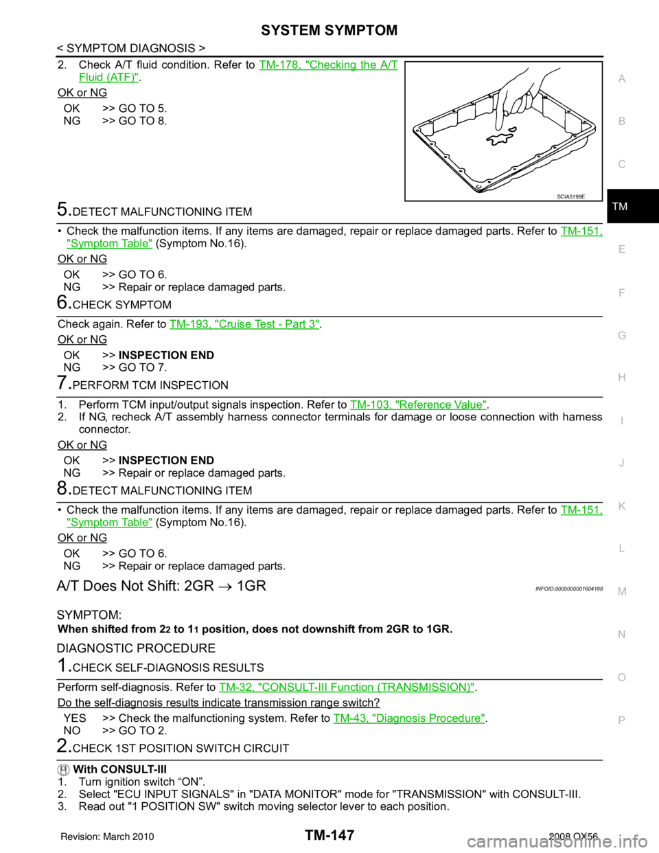
2. Check A/T fluid condition. Refer to TM-178, "Checking the A/T
Fluid (ATF)".
OK or NG
OK >> GO TO 5.
NG >> GO TO 8.
5.DETECT MALFUNCTIONING ITEM
• Check the malfunction items. If any items are damaged, repair or replace damaged parts. Refer to TM-151,
"Symptom Table" (Symptom No.16).
OK or NG
OK >> GO TO 6.
NG >> Repair or replace damaged parts.
6.CHECK SYMPTOM
Check again. Refer to TM-193, "
Cruise Test - Part 3".
OK or NG
OK >> INSPECTION END
NG >> GO TO 7.
7.PERFORM TCM INSPECTION
1. Perform TCM input/output signals inspection. Refer to TM-103, "
Reference Value".
2. If NG, recheck A/T assembly harness connector terminals for damage or loose connection with harness connector.
OK or NG
OK >> INSPECTION END
NG >> Repair or replace damaged parts.
8.DETECT MALFUNCTIONING ITEM
• Check the malfunction items. If any items are damaged, repair or replace damaged parts. Refer to TM-151,
"Symptom Table" (Symptom No.16).
OK or NG
OK >> GO TO 6.
NG >> Repair or replace damaged parts.
A/T Does Not Shift: 2GR → 1GRINFOID:0000000001604198
SYMPTOM:
When shifted from 22 to 11 position, does not downshift from 2GR to 1GR.
DIAGNOSTIC PROCEDURE
1.CHECK SELF-DIAGNOSIS RESULTS
Perform self-diagnosis. Refer to TM-32, "
CONSULT-III Function (TRANSMISSION)".
Do the self-diagnosis results i ndicate transmission range switch?
YES >> Check the malfunctioning system. Refer to TM-43, "Diagnosis Procedure".
NO >> GO TO 2.
2.CHECK 1ST POSITION SWITCH CIRCUIT
With CONSULT-III
1. Turn ignition switch “ON”.
2. Select "ECU INPUT SIGNALS" in "DATA MONITO R" mode for "TRANSMISSION" with CONSULT-III.
3. Read out "1 POSITION SW" switch mo ving selector lever to each position.
SCIA5199E
Revision: March 2010 2008 QX56
Page 3696 of 4083
SYSTEM SYMPTOMTM-149
< SYMPTOM DIAGNOSIS >
CEF
G H
I
J
K L
M A
B
TM
N
O P
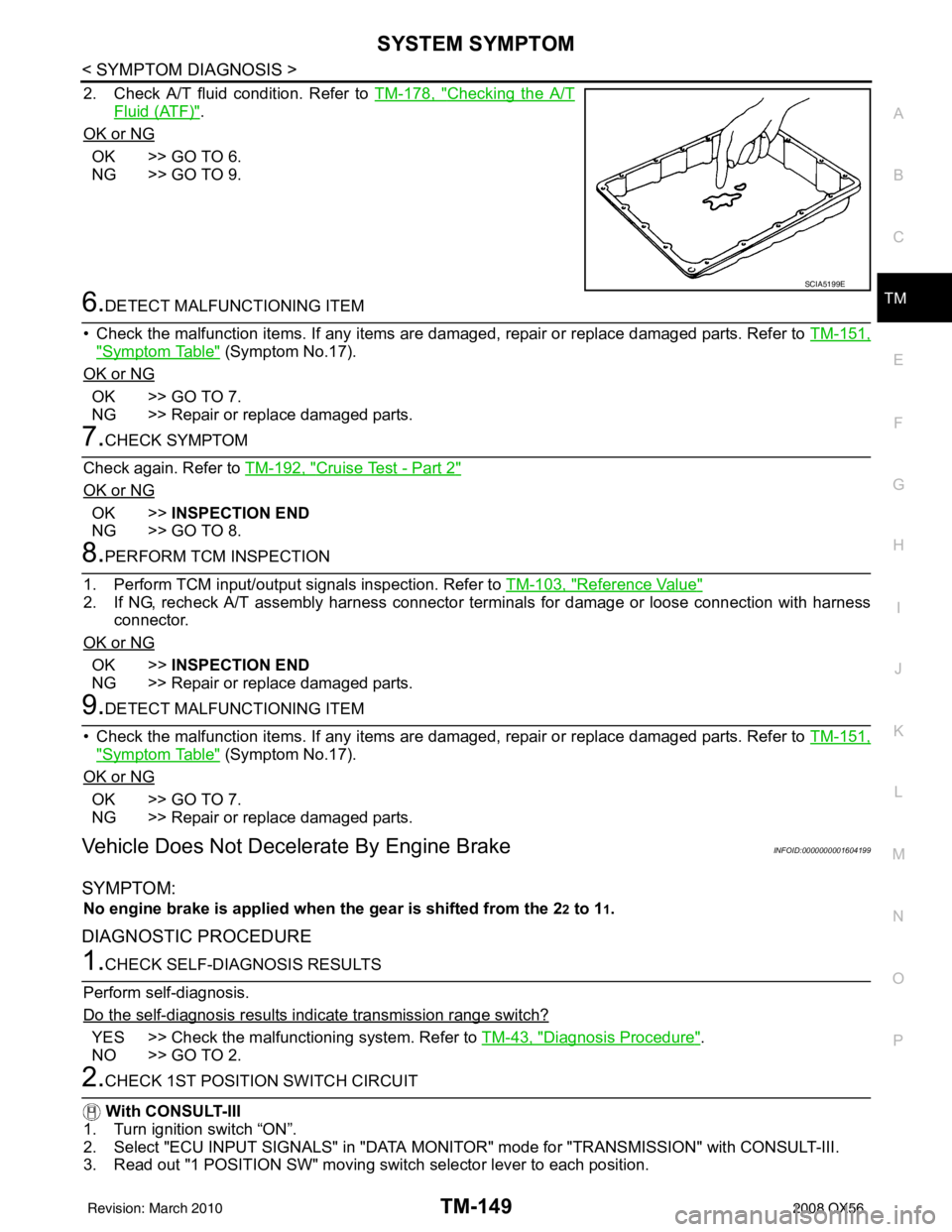
2. Check A/T fluid condition. Refer to TM-178, "Checking the A/T
Fluid (ATF)".
OK or NG
OK >> GO TO 6.
NG >> GO TO 9.
6.DETECT MALFUNCTIONING ITEM
• Check the malfunction items. If any items are damaged, repair or replace damaged parts. Refer to TM-151,
"Symptom Table" (Symptom No.17).
OK or NG
OK >> GO TO 7.
NG >> Repair or replace damaged parts.
7.CHECK SYMPTOM
Check again. Refer to TM-192, "
Cruise Test - Part 2"
OK or NG
OK >>INSPECTION END
NG >> GO TO 8.
8.PERFORM TCM INSPECTION
1. Perform TCM input/output signals inspection. Refer to TM-103, "
Reference Value"
2. If NG, recheck A/T assembly harness connector terminals for damage or loose connection with harness
connector.
OK or NG
OK >> INSPECTION END
NG >> Repair or replace damaged parts.
9.DETECT MALFUNCTIONING ITEM
• Check the malfunction items. If any items are damaged, repair or replace damaged parts. Refer to TM-151,
"Symptom Table" (Symptom No.17).
OK or NG
OK >> GO TO 7.
NG >> Repair or replace damaged parts.
Vehicle Does Not Decelerate By Engine BrakeINFOID:0000000001604199
SYMPTOM:
No engine brake is applied when the gear is shifted from the 22 to 11.
DIAGNOSTIC PROCEDURE
1.CHECK SELF-DIAGNOSIS RESULTS
Perform self-diagnosis.
Do the self-diagnosis results i ndicate transmission range switch?
YES >> Check the malfunctioning system. Refer to TM-43, "Diagnosis Procedure".
NO >> GO TO 2.
2.CHECK 1ST POSITION SWITCH CIRCUIT
With CONSULT-III
1. Turn ignition switch “ON”.
2. Select "ECU INPUT SIGNALS" in "DATA MONITO R" mode for "TRANSMISSION" with CONSULT-III.
3. Read out "1 POSITION SW" moving switch selector lever to each position.
SCIA5199E
Revision: March 2010 2008 QX56
Page 3721 of 4083
TM-174
< PRECAUTION >
PRECAUTIONS
5. When the repair work is completed, return the ignition switch to the ″LOCK ″ position before connecting
the battery cables. (At this time, the steering lock mechanism will engage.)
6. Perform a self-diagnosis check of a ll control units using CONSULT-III.
Precaution for On Board Diagnosis (OBD) System of A/T and EngineINFOID:0000000001531485
The ECM has an on board diagnostic system. It will light up the malfunction indicator lamp (MIL) to warn the
driver of a malfunction causing emission deterioration.
CAUTION:
• Be sure to turn the ignition switch “OFF” and disconnect the negative battery cable before any repair
or inspection work. The open/short circuit of related switches, sensors, solenoid valves, etc. Will
cause the MIL to light up.
• Be sure to connect and lock the connectors secure ly after work. A loose (unlocked) connector will
cause the MIL to light up due to an open circuit. (Be sure the connector is free from water, grease,
dirt, bent terminals, etc.)
• Be sure to route and secure th e harnesses properly after work. Interference of the harness with a
bracket, etc. May cause the MIL to light up due to a short circuit.
• Be sure to connect rubber tubes properly afte r work. A misconnected or disconnected rubber tube
may cause the MIL to light up due to a malfunction of the EGR system or fuel injection system, etc.
• Be sure to erase the unnecessary malfunction informa tion (repairs completed) from the TCM and
ECM before returning the vehicle to the customer.
PrecautionINFOID:0000000001531486
NOTE:
If any malfunctions occur in the RE5R05A model tr ansmission, replace the entire transmission assem-
bly.
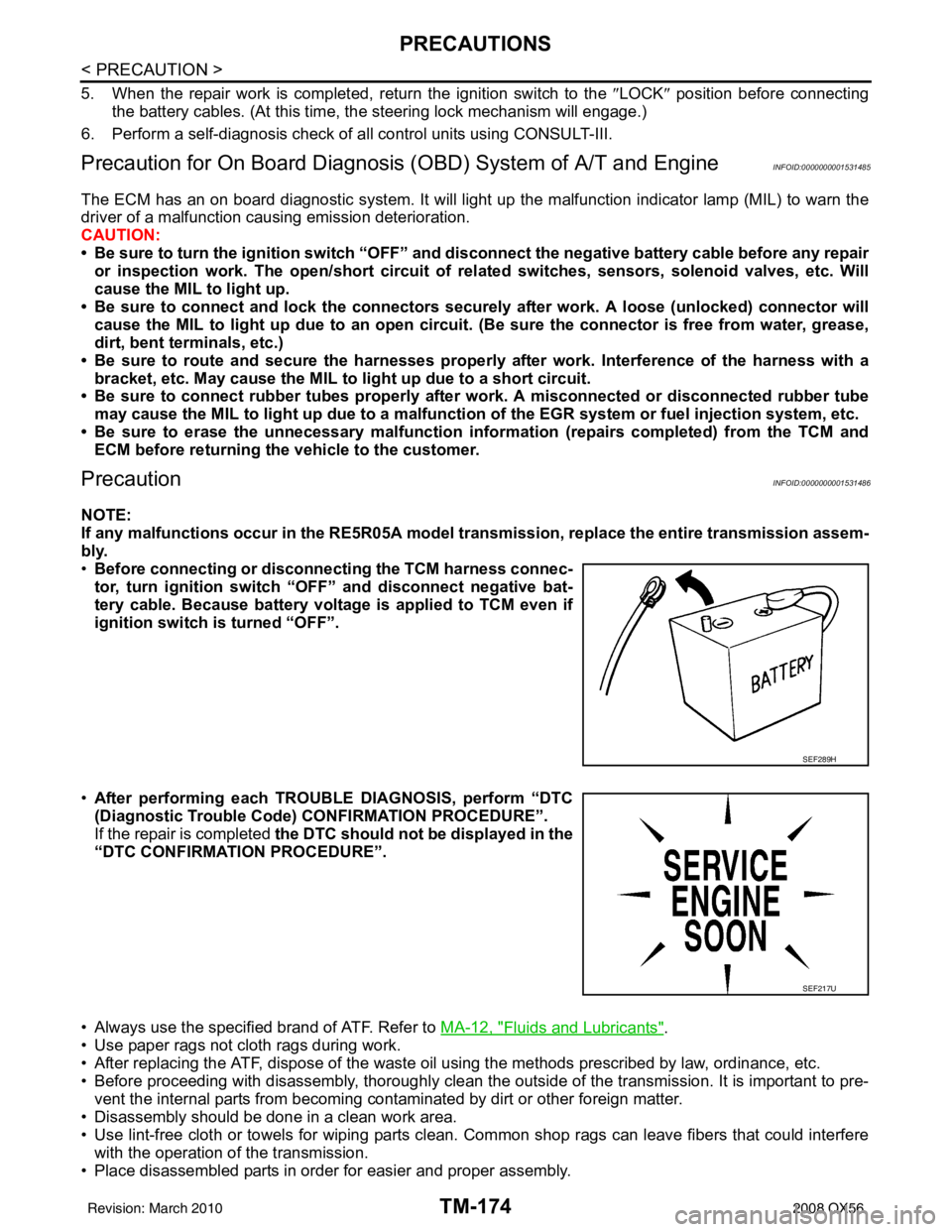
• Before connecting or disconn ecting the TCM harness connec-
tor, turn ignition switch “O FF” and disconnect negative bat-
tery cable. Because battery voltage is applied to TCM even if
ignition switch is turned “OFF”.
• After performing each TROUBLE DIAGNOSIS, perform “DTC
(Diagnostic Trouble Code) CONFIRMATION PROCEDURE”.
If the repair is completed the DTC should not be displayed in the
“DTC CONFIRMATION PROCEDURE”.
• Always use the specified brand of ATF. Refer to MA-12, "
Fluids and Lubricants".
• Use paper rags not cloth rags during work.
• After replacing the ATF, dispose of the waste oil using the methods prescribed by law, ordinance, etc.
• Before proceeding with disassembly, thoroughly clean the outside of the transmission. It is important to pre- vent the internal parts from becoming cont aminated by dirt or other foreign matter.
• Disassembly should be done in a clean work area.
• Use lint-free cloth or towels for wiping parts clean. Common shop rags can leave fibers that could interfere
with the operation of the transmission.
• Place disassembled parts in order for easier and proper assembly.
SEF289H
SEF217U
Revision: March 2010 2008 QX56
Page 3732 of 4083
STALL TESTTM-185
< ON-VEHICLE MAINTENANCE >
CEF
G H
I
J
K L
M A
B
TM
N
O P
STALL TEST
Inspection and JudgmentINFOID:0000000001696156
A/T FLUID CHECK
Fluid Leakage and Fluid Level Check
• Inspect for fluid leakage and check the fluid level. Refer to TM-178, "Checking the A/T Fluid (ATF)".
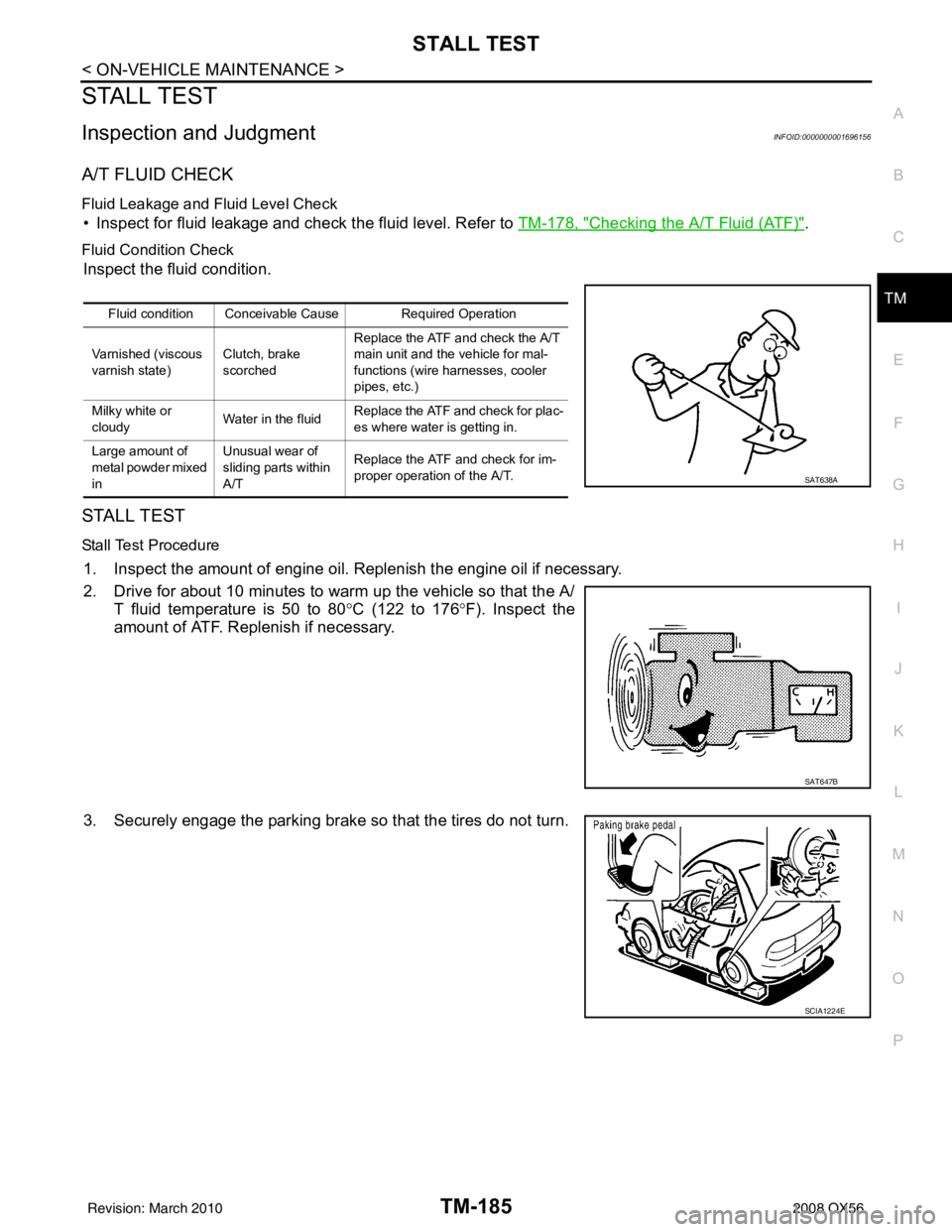
Fluid Condition Check
Inspect the fluid condition.
STALL TEST
Stall Test Procedure
1. Inspect the amount of engine oil. Replenish the engine oil if necessary.
2. Drive for about 10 minutes to warm up the vehicle so that the A/
T fluid temperature is 50 to 80 °C (122 to 176 °F). Inspect the
amount of ATF. Replenish if necessary.
3. Securely engage the parking brake so that the tires do not turn.
Fluid condition Conceivable Cause Required Operation
Varnished (viscous
varnish state) Clutch, brake
scorchedReplace the ATF and check the A/T
main unit and the vehicle for mal-
functions (wire harnesses, cooler
pipes, etc.)
Milky white or
cloudy Water in the fluidReplace the ATF and check for plac-
es where water is getting in.
Large amount of
metal powder mixed
in Unusual wear of
sliding parts within
A/T
Replace the ATF and check for im-
proper operation of the A/T.
SAT638A
SAT647B
SCIA1224E
Revision: March 2010
2008 QX56
Page 3734 of 4083
LINE PRESSURE TESTTM-187
< ON-VEHICLE MAINTENANCE >
CEF
G H
I
J
K L
M A
B
TM
N
O P
LINE PRESSURE TEST
Inspection and JudgmentINFOID:0000000001696157
LINE PRESSURE TEST
Line Pressure Test Port
Line Pressure Test Procedure
1. Inspect the amount of engine oil and replenish if necessary.
2. Drive the car for about 10 minutes to warm it up so that the ATF reaches in range of 50 to 80 °C (122 to
176° F), then inspect the amount of ATF and replenish if necessary.
NOTE:
The automatic fluid temperature rises in range of 50 to 80 °C (122 to 176° F) during 10 minutes of
driving.
3. After warming up remove the oil pressure detection plug and install the Tool.
CAUTION:
When using the oil pressure ga uge, be sure to use the O-
ring attached to the oil pressure detection plug.
4. Securely engage the parking brake so that the tires do not turn.
SCIA2187E
SCIA5309E
SCIA1224E
Revision: March 2010 2008 QX56
Page 3744 of 4083
AIR BREATHER HOSETM-197
< ON-VEHICLE REPAIR >
CEF
G H
I
J
K L
M A
B
TM
N
O P
AIR BREATHER HOSE
Removal and InstallationINFOID:0000000004917433
VK56DE Models 2WD
CAUTION:
• Install air breather hose with paint mark at upper side.
• When installing the air breather hose, do not crush or block by folding or bending the hose.
• When inserting the hose to the tran smission tube, be sure to insert it fully until its end reaches the
tube bend portion.
• Make sure clip is securely installed to bracket.
VK56DE Models 4WD
LCIA0331E
Revision: March 2010 2008 QX56
Page 3745 of 4083
TM-198
< ON-VEHICLE REPAIR >
AIR BREATHER HOSE
CAUTION:
• Install air breather hose with paint mark at upper side.
• When installing the air breather hose, do not crush or block by folding or bending the hose.
• When inserting the hose to the tran smission tube, be sure to insert it fully until its end reaches the
tube bend portion.
• Make sure clip is securely installed to bracket.
Revision: March 2010 2008 QX56
Page 3754 of 4083
CONTROL VALVE WITH TCMTM-207
< ON-VEHICLE REPAIR >
CEF
G H
I
J
K L
M A
B
TM
N
O P
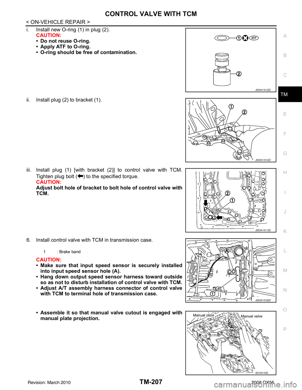
i. Install new O-ring (1) in plug (2). CAUTION:
• Do not reuse O-ring.
• Apply ATF to O-ring.
• O-ring should be free of contamination.
ii. Install plug (2) to bracket (1).
iii. Install plug (1) [with bracket (2)] to control valve with TCM. Tighten plug bolt ( ) to the specified torque.
CAUTION:
Adjust bolt hole of bracket to bolt hole of control valve with
TCM.
6. Install control valve with TCM in transmission case. CAUTION:
• Make sure that input speed sensor is securely installed
into input speed sensor hole (A).
• Hang down output speed sensor harness toward outside
so as not to disturb installati on of control valve with TCM.
• Adjust A/T assembly harness connector of control valve with TCM to terminal hole of transmission case.
• Assemble it so that manual valve cutout is engaged with
manual plate projection.
JSDIA1313ZZ
JSDIA1312ZZ
JSDIA1311ZZ
1 : Brake band
JSDIA1318ZZ
SCIA5142E
Revision: March 2010 2008 QX56