2008 INFINITI FX35 service
[x] Cancel search: servicePage 3743 of 3924

SRS-6
< SERVICE INFORMATION >
DTC INDEX
B1209 FRONTAL COLLISIONSRS-47, "For Frontal Collision"
B1210 SIDE COLLISION SRS-48, "For Side Collision"
DTC Items (CONSULT screen terms) Reference
3AA93ABC3ACD3AC03ACA3AC03AC63AC53A913A773A893A873A873A8E3A773A983AC73AC93AC03AC3
3A893A873A873A8F3A773A9D3AAF3A8A3A8C3A863A9D3AAF3A8B3A8C
Page 3744 of 3924

PRECAUTIONSSRS-7
< SERVICE INFORMATION >
C
DE
F
G
I
J
K L
M A
B
SRS
N
O P
PRECAUTIONS
Precaution for Supplemental Restraint System (SRS) "AIR BAG" and "SEAT BELT
PRE-TENSIONER"
INFOID:0000000001612877
The Supplemental Restraint System such as “A IR BAG” and “SEAT BELT PRE-TENSIONER”, used along
with a front seat belt, helps to reduce the risk or severi ty of injury to the driver and front passenger for certain
types of collision. This system includes seat belt switch inputs and dual stage front air bag modules. The SRS
system uses the seat belt switches to determine the front air bag deployment, and may only deploy one front
air bag, depending on the severity of a collision and whether the front occupants are belted or unbelted.
Information necessary to service the system safely is included in the “SUPPLEMENTAL RESTRAINT SYS-
TEM” and “SEAT BELTS” of this Service Manual.
WARNING:
• To avoid rendering the SRS inoper ative, which could increase the risk of personal injury or death in
the event of a collision which would result in air bag inflation, all maintenance must be performed by
an authorized NISSAN/INFINITI dealer.
Improper maintenance, including in correct removal and installation of the SRS, can lead to personal
injury caused by unintentional act ivation of the system. For removal of Spiral Cable and Air Bag
Module, see the “SUPPLEMEN TAL RESTRAINT SYSTEM”.
Do not use electrical test equipm ent on any circuit related to the SRS unless instructed to in this
Service Manual. SRS wiring harnesses can be identi fied by yellow and/or orange harnesses or har-
ness connectors.
Precaution for SRS "AIR BAG" and "SEAT BELT PRE-TENSIONER" Service
INFOID:0000000001327741
Do not use electrical test equipment to check SRS ci rcuits unless instructed to in this Service Manual.
Before servicing the SRS, turn ignition switch OFF, disconnect both battery cables and wait at least 3 min-
utes.
For approximately 3 minutes after the cables are remov ed, it is still possible for the air bag and seat belt pre-
tensioner to deploy. Therefore, do not work on any SR S connectors or wires until at least 3 minutes have
passed.
Diagnosis sensor unit must always be installed with their arrow marks “ ⇐” pointing towards the front of the
vehicle for proper operation. Also check diagnosis sensor unit for cracks, deformities or rust before installa-
tion and replace as required.
The spiral cable must be aligned with the neutral position since its rotations are limited. Do not turn steering
wheel and column after removal of steering gear.
Handle air bag module carefully. Always place driver and front passenger air bag modules with the pad side facing upward and seat mounted front side air bag module standing with the stud bolt side facing down.
Conduct self-diagnosis to check entire SRS for proper function after replacing any components.
After air bag inflates, the front instrument panel assembly should be replaced if damaged.
Always replace instrument panel pad following front passenger air bag deployment.
Disposal, recycling, and transportation of air bag m odules and seat belt pre-tensioners should be performed
in compliance with applicable federal, state and local laws and regulations.
Occupant Classification System PrecautionINFOID:0000000001327742
Replace occupant classification system control uni t and passenger front seat cushion as an assembly.
Refer to Refer to Service Manual .
3AA93ABC3ACD3AC03ACA3AC03AC63AC53A913A773A893A873A873A8E3A773A983AC73AC93AC03AC3
3A893A873A873A8F3A773A9D3AAF3A8A3A8C3A863A9D3AAF3A8B3A8C
Page 3745 of 3924
SRS-8
< SERVICE INFORMATION >
PREPARATION
PREPARATION
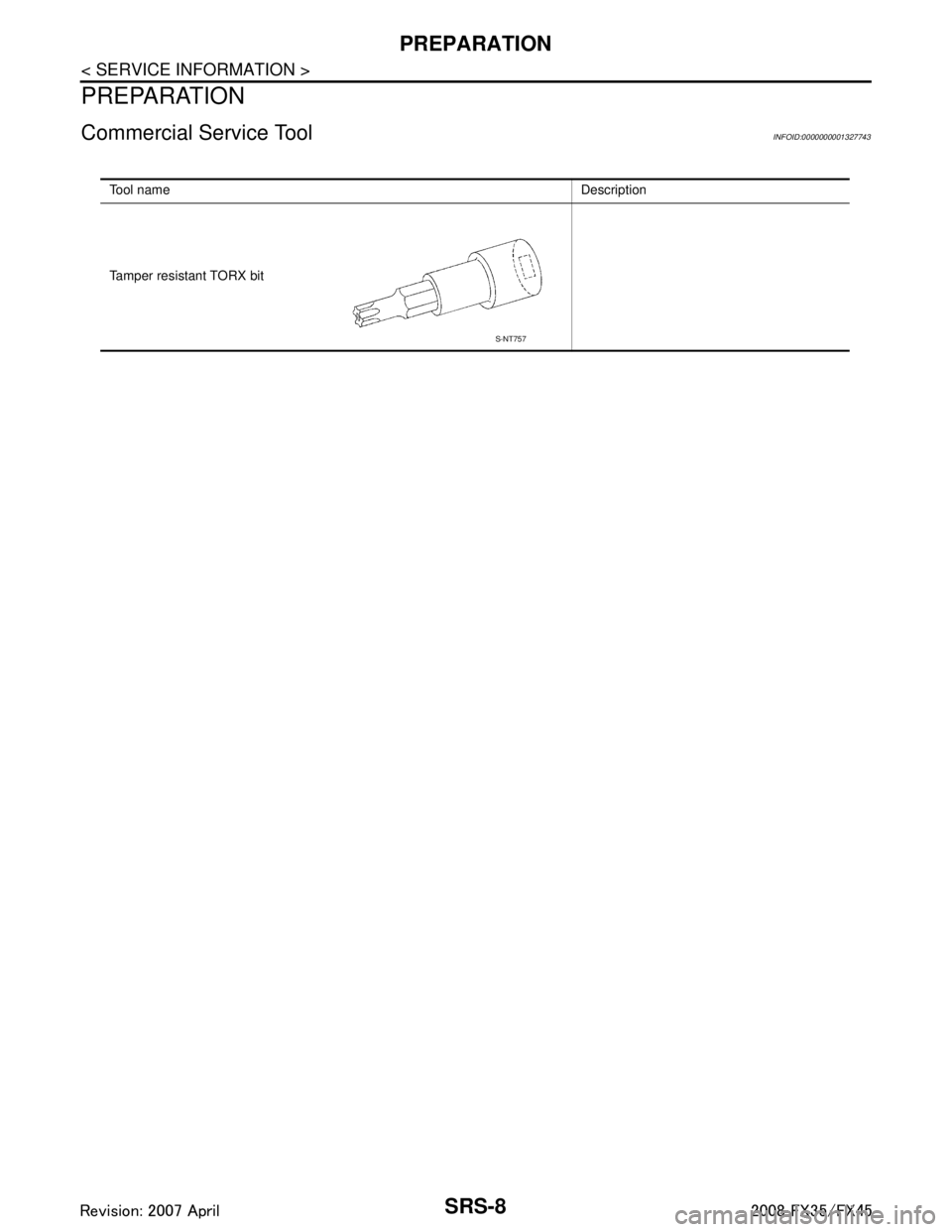
Commercial Service ToolINFOID:0000000001327743
Tool name Description
Tamper resistant TORX bit
S-NT757
3AA93ABC3ACD3AC03ACA3AC03AC63AC53A913A773A893A873A873A8E3A773A983AC73AC93AC03AC3
3A893A873A873A8F3A773A9D3AAF3A8A3A8C3A863A9D3AAF3A8B3A8C
Page 3746 of 3924
SUPPLEMENTAL RESTRAINT SYSTEM (SRS)SRS-9
< SERVICE INFORMATION >
C
DE
F
G
I
J
K L
M A
B
SRS
N
O P
SUPPLEMENTAL RESTRAINT SYSTEM (SRS)
SRS ConfigurationINFOID:0000000001524154
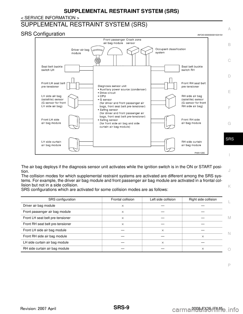
The air bag deploys if the diagnosis sensor unit activates while the ignition switch is in the ON or START posi-
tion.
The collision modes for which supplemental restraint systems are activated are different among the SRS sys-
tems. For example, the driver air bag module and front passenger air bag module are activated in a frontal col-
lision but not in a side collision.
SRS configurations which are activated for some collision modes are as follows:
PHIA1120E
SRS configuration Frontal collision Left side collision Right side collision
Driver air bag module ×——
Front passenger air bag module ×——
Front LH seat belt pre-tensioner ×——
Front RH seat belt pre-tensioner ×——
Front LH side air bag module — ×—
Front RH side air bag module — — ×
LH side curtain air bag module — ×—
RH side curtain air bag module — — ×
3AA93ABC3ACD3AC03ACA3AC03AC63AC53A913A773A893A873A873A8E3A773A983AC73AC93AC03AC3
3A893A873A873A8F3A773A9D3AAF3A8A3A8C3A863A9D3AAF3A8B3A8C
Page 3747 of 3924
SRS-10
< SERVICE INFORMATION >
SUPPLEMENTAL RESTRAINT SYSTEM (SRS)
Front Seat Belt Pre-te nsioner with Load Limiter
INFOID:0000000001524155
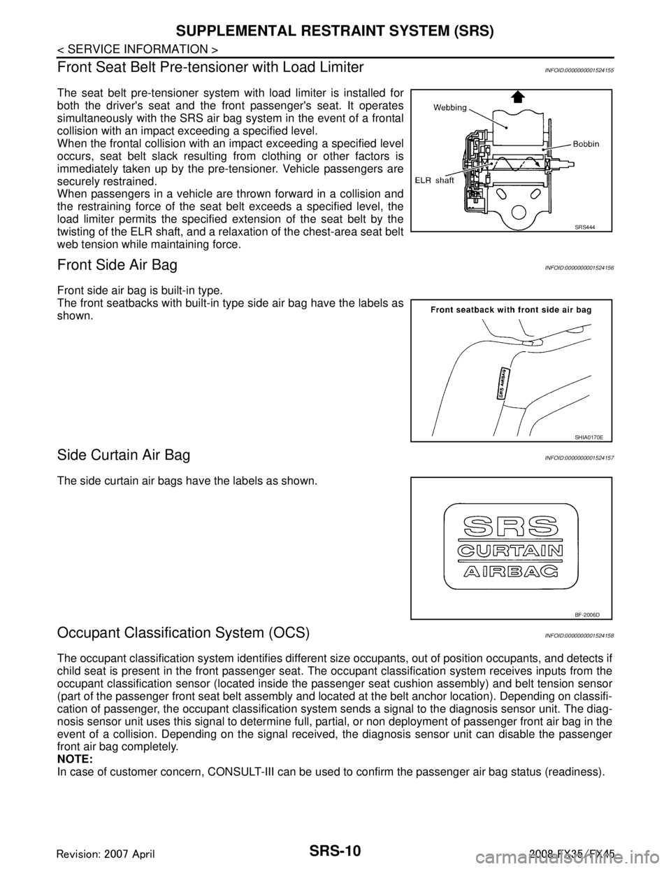
The seat belt pre-tensioner system wi th load limiter is installed for
both the driver's seat and the front passenger's seat. It operates
simultaneously with the SRS air bag system in the event of a frontal
collision with an impact exceeding a specified level.
When the frontal collision with an impact exceeding a specified level
occurs, seat belt slack resulting from clothing or other factors is
immediately taken up by the pre-tensioner. Vehicle passengers are
securely restrained.
When passengers in a vehicle are thrown forward in a collision and
the restraining force of the seat belt exceeds a specified level, the
load limiter permits the specified extension of the seat belt by the
twisting of the ELR shaft, and a relaxation of the chest-area seat belt
web tension while maintaining force.
Front Side Air BagINFOID:0000000001524156
Front side air bag is built-in type.
The front seatbacks with built-in type side air bag have the labels as
shown.
Side Curtain Air BagINFOID:0000000001524157
The side curtain air bags have the labels as shown.
Occupant Classification System (OCS)INFOID:0000000001524158
The occupant classification system identifies different si ze occupants, out of position occupants, and detects if
child seat is present in the front passenger seat. The oc cupant classification system receives inputs from the
occupant classification sensor (located inside the pa ssenger seat cushion assembly) and belt tension sensor
(part of the passenger front seat belt assembly and located at the belt anchor location). Depending on classifi-
cation of passenger, the occupant clas sification system sends a signal to the diagnosis sensor unit. The diag-
nosis sensor unit uses this signal to determine full, pa rtial, or non deployment of passenger front air bag in the
event of a collision. Depending on the signal received, the diagnosis sensor unit can disable the passenger
front air bag completely.
NOTE:
In case of customer concern, CONSULT-III can be used to confirm the passenger air bag status (readiness).
SRS444
SHIA0170E
BF-2006D
3AA93ABC3ACD3AC03ACA3AC03AC63AC53A913A773A893A873A873A8E3A773A983AC73AC93AC03AC3
3A893A873A873A8F3A773A9D3AAF3A8A3A8C3A863A9D3AAF3A8B3A8C
Page 3748 of 3924
SUPPLEMENTAL RESTRAINT SYSTEM (SRS)SRS-11
< SERVICE INFORMATION >
C
DE
F
G
I
J
K L
M A
B
SRS
N
O P
Passenger Air Bag Status ConditionINFOID:0000000001524159
NOTE:
Passenger does not meet Ocuupant classification System specifications for passenger air bag activation.
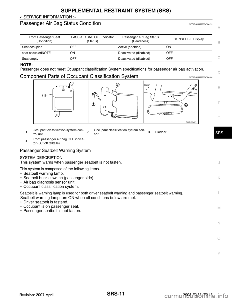
Component Parts of Occupant Classification SystemINFOID:0000000001524160
Passenger Seatbelt Warning System
SYSTEM DESCRIPTION
This system warns when passenger seatbelt is not fasten.
This system is composed of the following items.
Seatbelt warning lamp.
Seatbelt buckle switch (passenger side).
Air bag diagnosis sensor unit.
Occupant classification system.
Seatbelt is warning lamp is used for both driver seatbelt warning and passenger seatbelt warning.
Seatbelt warning lamp turs ON when all conditions below are met.
Driver seatbelt is fastend.
Occupant is on passenger seat.
Passenger seatbelt is not fasten.
Front Passenger Seat
(Condition) PASS AIR BAG OFF Indicator
(Status) Passenger Air Bag Status
(Readiness) CONSULT-III Display
Seat occupied OFF Active (enabled) ON
seat occupiedNOTE ON Deactivated (disabled) OFF
Seat empty OFF Deactivated (disabled) OFF
PHIA1334E
1. Occupant classification system con-
trol unit 2.Occupant classification system sen-
sor 3. Bladder
4. Front passenger air bag OFF indica-
tor (Cut off telltaile)
3AA93ABC3ACD3AC03ACA3AC03AC63AC53A913A773A893A873A873A8E3A773A983AC73AC93AC03AC3
3A893A873A873A8F3A773A9D3AAF3A8A3A8C3A863A9D3AAF3A8B3A8C
Page 3749 of 3924

SRS-12
< SERVICE INFORMATION >
TROUBLE DIAGNOSIS
TROUBLE DIAGNOSIS
Trouble Diagnosis IntroductionINFOID:0000000001524161
CAUTION:
Do not use electrical test equipment on any circuit related to the SRS unless instructed in this Ser-
vice Manual. SRS wiring harnesses can be identifi ed by yellow and/or orange harnesses or harness
connectors.
Do not repair, splice or modify the SRS wiring harn ess. If the harness is damaged, replace it with a
new one.
Keep ground portion clean.
DIAGNOSIS FUNCTION
The SRS self-diagnostic results can be read by us ing “AIR BAG” warning lamp and/or CONSULT-III.
The User mode is exclusively prepared for the customer (driver). This mode warns the driver of a system mal-
function through the operation of the “AIR BAG” warning lamp.
The Diagnosis mode allows the technician to locate and inspect the malfunctioning part.
The mode applications for the “AIR BAG” wa rning lamp and CONSULT-III are as follows:
HOW TO PERFORM TROUBLE DIAGNOSIS FOR QUICK AND ACCURATE REPAIR
A good understanding of the malfunction conditions can make troubleshooting faster and more accurate.
In general, each customer feels differently about a malf unction. It is important to fully understand the symp-
toms or conditions for a customer complaint.
Information from Customer
WHAT..... Vehicle model
WHEN..... Date, Frequencies
WHERE..... Road conditions
HOW..... Operating conditions, Symptoms
Preliminary Check
Make sure the following parts are in good order.
Battery (Refer to SC-4, "
How to Handle Battery".)
Fuse (Refer to SRS-16, "
Wiring Diagram - SRS -".)
System component-to-harness connections
Work Flow
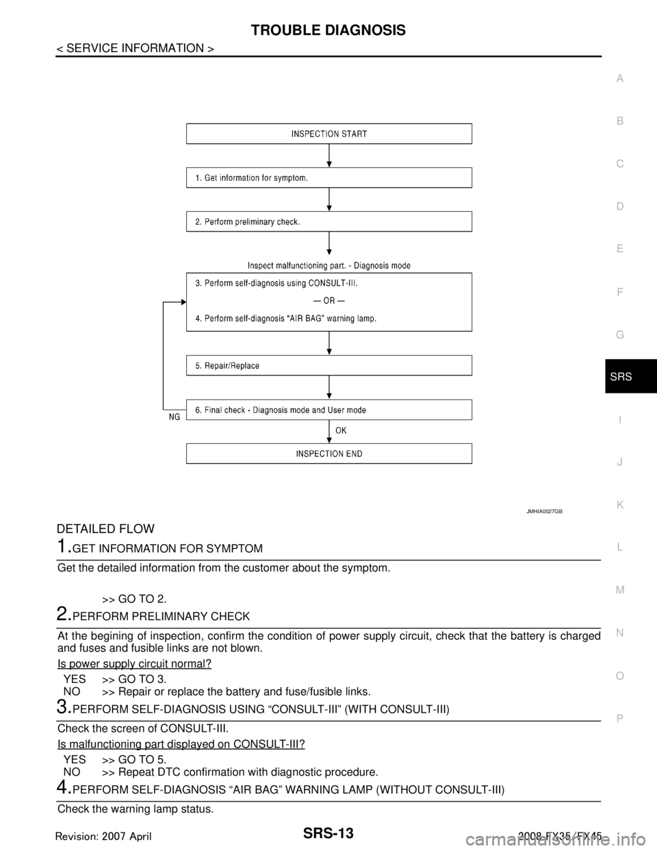
OVERALL SEQUENCE
User mode Diagnosis mode Display type
“AIR BAG” warning lamp X X ON-OFF operation CONSULT-III — X Monitoring
3AA93ABC3ACD3AC03ACA3AC03AC63AC53A913A773A893A873A873A8E3A773A983AC73AC93AC03AC3
3A893A873A873A8F3A773A9D3AAF3A8A3A8C3A863A9D3AAF3A8B3A8C
Page 3750 of 3924
TROUBLE DIAGNOSISSRS-13
< SERVICE INFORMATION >
C
DE
F
G
I
J
K L
M A
B
SRS
N
O P
DETAILED FLOW
1.GET INFORMATION FOR SYMPTOM
Get the detailed information from the customer about the symptom.
>> GO TO 2.
2.PERFORM PRELIMINARY CHECK
At the begining of inspection, confirm the condition of pow er supply circuit, check that the battery is charged
and fuses and fusible links are not blown.
Is power supply circuit normal?
YES >> GO TO 3.
NO >> Repair or replace the battery and fuse/fusible links.
3.PERFORM SELF-DIAGNOSIS USING “C ONSULT-III” (WITH CONSULT-III)
Check the screen of CONSULT-III.
Is malfunctioning part displayed on CONSULT-III?
YES >> GO TO 5.
NO >> Repeat DTC confirmation with diagnostic procedure.
4.PERFORM SELF-DIAGNOSIS “AIR BAG” WA RNING LAMP (WITHOUT CONSULT-III)
Check the warning lamp status.
JMHIA0027GB
3AA93ABC3ACD3AC03ACA3AC03AC63AC53A913A773A893A873A873A8E3A773A983AC73AC93AC03AC3
3A893A873A873A8F3A773A9D3AAF3A8A3A8C3A863A9D3AAF3A8B3A8C