2008 Hyundai Santa Fe Low side
[x] Cancel search: Low sidePage 304 of 355
6
DO-IT-YOURSELF MAINTENANCE
18
!
CAUTION:
When replacing a fusible link, never use
anything but a new fusible link with the
same or lower amperage rating. Never
use a piece of wire or a higher-rated
fusible link. This could result in serious
damage and create a fire hazard.
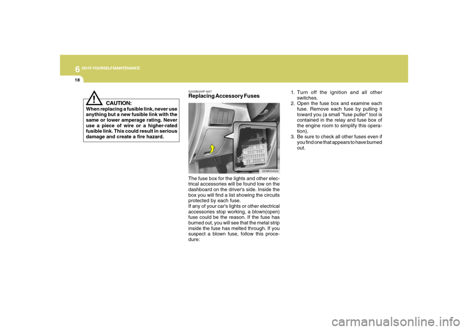
G200B02HP-AATReplacing Accessory Fuses
OCM054002
The fuse box for the lights and other elec-
trical accessories will be found low on the
dashboard on the driver's side. Inside the
box you will find a list showing the circuits
protected by each fuse.
If any of your car's lights or other electrical
accessories stop working, a blown(open)
fuse could be the reason. If the fuse has
burned out, you will see that the metal strip
inside the fuse has melted through. If you
suspect a blown fuse, follow this proce-
dure:1. Turn off the ignition and all other
switches.
2. Open the fuse box and examine each
fuse. Remove each fuse by pulling it
toward you (a small "fuse puller" tool is
contained in the relay and fuse box of
the engine room to simplify this opera-
tion).
3. Be sure to check all other fuses even if
you find one that appears to have burned
out.
Page 306 of 355
6
DO-IT-YOURSELF MAINTENANCE
20
G200C01CM-GATPower connectorNOTE:
o If the power connector is pulled out of
the fuse panel, the warning chime,
audio, clock and interior lamps, etc.,
will not operate. The following items
must be reset after replacement.
- Digital Clock
- Trip computer
- Automatic heating and cooling con-
trol system
- Audio
o Even though the power connector is
pulled out, the battery can still be
discharged by operation of the head-
lights or other electrical devices.
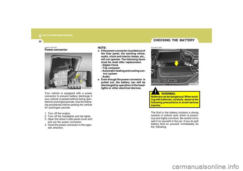
Your vehicle is equipped with a power
connector to prevent battery discharge if
your vehicle is parked without being oper-
ated for prolonged periods. Use the follow-
ing procedures before parking the vehicle
for prolonged periods.
1. Turn off the engine.
2. Turn off the headlights and tail lights.
3. Open the driver’s side panel cover and
pull out the power connector.
4. Insert the power connector in the oppo-
site direction.
OCM055026L
CHECKING THE BATTERY!
G210A01A-AAT
WARNING:
Batteries can be dangerous! When work-
ing with batteries, carefully observe the
following precautions to avoid serious
injuries.
The fluid in the battery contains a strong
solution of sulfuric acid, which is poison-
ous and highly corrosive. Be careful not to
spill it on yourself or the car. If you do spill
battery fluid on yourself, immediately do
the following:
OCM055016
Page 310 of 355
6
DO-IT-YOURSELF MAINTENANCE
24
REPLACEMENT OF LIGHT
BULBSG260A01CM-AATBefore attempting to replace a light bulb,
be sure the switch is turned to the "OFF"
position.
The next paragraph shows how to reach
the light bulbs so they may be changed. Be
sure to replace the burned-out bulb with
one of the same number and wattage
rating.
CAUTION:
o Keep the lamps out of contact with
petroleum products, such as oil, gaso-
line, etc.
o After heavy, driving rain or washing,
headlight and taillight lenses could
appear frosty. This condition is
caused by the temperature difference
between the lamp inside and outside.
This is similar to the condensation on
your windows inside your vehicle
during the rain and doesn’t indicate a
problem with your vehicle. If the water
leaks into the lamp bulb circuitry, have
the vehicle checked by an Authorized
Hyundai Dealer.
!
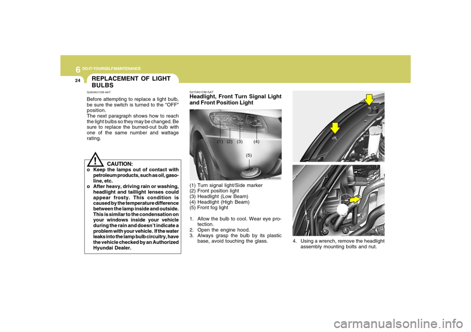
G270A01CM-GATHeadlight, Front Turn Signal Light
and Front Position Light(1) Turn signal light/Side marker
(2) Front position light
(3) Headlight (Low Beam)
(4) Headlight (High Beam)
(5) Front fog light
1. Allow the bulb to cool. Wear eye pro-
tection.
2. Open the engine hood.
3. Always grasp the bulb by its plastic
base, avoid touching the glass.
OCM055020
(1)
(2) (3) (4)
(5)
OCM055008L
4. Using a wrench, remove the headlight
assembly mounting bolts and nut.
OCM055021L
Page 317 of 355
6
DO-IT-YOURSELF MAINTENANCE
31
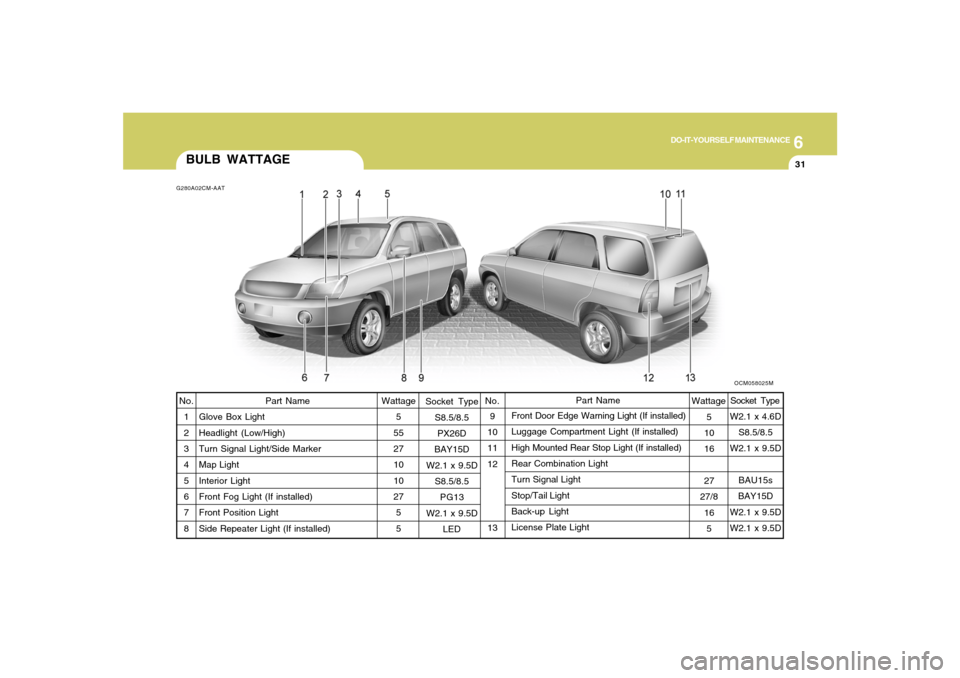
BULB WATTAGE
Socket Type
S8.5/8.5
PX26D
BAY15D
W2.1 x 9.5D
S8.5/8.5
PG13
W2.1 x 9.5D
LED9
10
11
12
13Front Door Edge Warning Light (If installed)
Luggage Compartment Light (If installed)
High Mounted Rear Stop Light (If installed)
Rear Combination Light
Turn Signal Light
Stop/Tail Light
Back-up Light
License Plate Light No.
1
2
3
4
5
6
7
8
Part Name
Glove Box Light
Headlight (Low/High)
Turn Signal Light/Side Marker
Map Light
Interior Light
Front Fog Light (If installed)
Front Position Light
Side Repeater Light (If installed)Wattage
5
55
27
10
10
27
5
5
G280A02CM-AAT
Wattage No.
OCM058025M
5
10
16
27
27/8
16
5
Socket Type
Part Name
W2.1 x 4.6D
S8.5/8.5
W2.1 x 9.5D
BAU15s
BAY15D
W2.1 x 9.5D
W2.1 x 9.5D
Page 320 of 355

6
DO-IT-YOURSELF MAINTENANCE
34
G200E01CM-AATInner Panel
OCM055024N
FUSE RATING
15A
25A
15A
10A
15A
10A
10A
10A
30A
10A
15A
10A
10A
10A
10A
10A
10ACIRCUIT PROTECTED
CIGARETTE LIGHTER
FRONT POWER OUTLET, REAR POWER OUTLET
CENTER POWER OUTLET
POWER OUTSIDE MIRROR SWITCH, AUDIO, ATM KEY LOCK CONTROL MODULE,
DIGITAL CLOCK
MULTIFUNCTION SWITCH, REAR WIPER CONTROL MODULE,REAR WIPER
MOTOR
RAIN SENSOR
RHEOSTAT, BCM, INSTRUMENT CLUSTER
A/C CONTROL MODULE, INCAR & HUMIDITY SENSOR, HIGH BLOWER RELAY,
REAR A/CON SWITCH, ICM RELAY BOX, AQS SENSOR, SUNROOF MOTOR,
BLOWER BELAY, ELECTRO CHROMIC MIRROR
BLOWER RELAY, BLOWER MOTOR, A/C CONTROL MODULE
A/C CONTROL MODULE
SRS CONTROL MODULE
PAB ON/OFF SWITCH, INSTRUMENT CLUSTER
HAZARD SWITCH
MULTIFUNTION SWITCH, STEERING ANGLE SENSOR, ESC SWITCH, ATM KEY
LOCK CONTROL MODULE SEAT WARMER MODULE
OIL LEVEL SENSOR MODULE, BCM
INSTRUMENT CLUSTER, PRE-EXCITATION RESISTOR, BCM, GENERATOR, SEMI
ACTIVE CONTROL MODULE (GASOLINE)
BURGLAR ALARM RELAY
C/LIGHTER
P/OUTLET
P/OUTLET
CTR
AUDIO #2
RR WIPER
IMS
BCM #2
A/CON 2
BLOWER
A/CON 1
A/BAG #1
A/BAG IND
T/SIG
ATM LOCK
BCM #1
CLUSTER
STARTFUSE
Page 323 of 355
7
EMISSION CONTROL SYSTEMS2
EMISSION CONTROL SYSTEM
H010B01A-AAT1. Crankcase Emission Control
SystemThe positive crankcase ventilation system
is employed to prevent air pollution caused
by blow-by gases being emitted from the
crankcase. This system supplies filtered
air to the crankcase through the air intake
hose. Inside the crankcase, the fresh air
mixes with blow-by gases, which then pass
through the PCV valve and into the induc-
tion system.
H010A01NF-AATYour Hyundai is equipped with an emis-
sion control system to meet all emission
regulations.
There are three emission control systems
which are as follows.
(1) Crankcase emission control system
(2) Evaporative emission control system
(3) Exhaust emission control system
In order to assure the proper function of the
emission control systems, it is recom-
mended that you have your car inspected
and maintained by an authorized Hyundai
dealer in accordance with the maintenance
schedule in this manual.
Caution for the Inspection and Mainte-
nance Test (With Electronic Stability
Control (ESC) system)
o To prevent the vehicle from misfiring
during dynamometer testing, turn the
Electronic Stability Control (ESC) sys-
tem off by pressing the ESC switch.
o After dynamometer testing is com-
pleted, turn the ESC system back on
by pressing the ESC switch again.
H010C01S-AAT2. Evaporative Emission Control (In-
cluding ORVR: Onboard Refuel-
ing Vapor Recovery) SystemThe Evaporative Emission Control Sys-
tem is designed to prevent fuel vapors from
escaping into the atmosphere.
(The ORVR system is designed to allow
the vapors from the fuel tank to be loaded
into a canister while refueling at the gas
station, preventing the escape of fuel va-
pors into the atmosphere.)CanisterFuel vapors generated inside the fuel tank
are absorbed and stored in the canister.
When the engine is running, the fuel va-
pors absorbed in the canister are drawn
into the induction system through the purge
control solenoid valve.
Cmhma-7.p653/17/2006, 10:29 AM 2
Page 331 of 355
8
CONSUMER INFORMATION, REPORTING SAFETY DEFECTS & BINDING ARBITRATION OF WARRANTY CLAIMS6
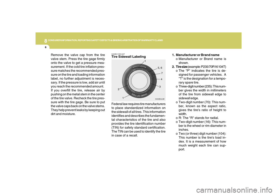
1. Manufacturer or Brand name
o Manufacturer or Brand name is
shown.
2. Tire size (example: P235/70R16 104T)
o The "P" indicates the tire is de-
signed for passenger vehicles. A
"T" is the designation for a tempo-
rary spare tire.
o Three-digit number (235): This num-
ber gives the width in millimeters
of the tire from sidewall edge to
sidewall edge.
o Two-digit number (70): This num-
ber, known as the aspect ratio,
gives the tire's ratio of height to
width.
o R: The "R" stands for radial.
o Two-digit number (16): This num-
ber is the wheel or rim diameter in
inches.
o Two (or three) digit number (104):
This number is the tire's load in-
dex. It is a measurement of how
much weight each tire can sup-
port.
Federal law requires tire manufacturers
to place standardized information on
the sidewall of all tires. This information
identifies and describes the fundamen-
tal characteristics of the tire and also
provides the tire identification number
(TIN) for safety standard certification.
The TIN can be used to identify the tire
in case of a recall.I030B01CM-AATTire Sidewall Labeling
I030B04JM
1
234 5, 6
7
1
Remove the valve cap from the tire
valve stem. Press the tire gage firmly
onto the valve to get a pressure mea-
surement. If the cold tire inflation pres-
sure matches the recommended pres-
sure on the tire and loading information
label, no further adjustment is neces-
sary. If the pressure is low, add air until
you reach the recommended amount.
If you overfill the tire, release air by
pushing on the metal stem in the center
of the tire valve. Recheck the tire pres-
sure with the tire gage. Be sure to put
the valve caps back on the valve stems.
They help prevent leaks by keeping out
dirt and moisture.
Page 335 of 355
8
CONSUMER INFORMATION, REPORTING SAFETY DEFECTS & BINDING ARBITRATION OF WARRANTY CLAIMS
10
I050A01CM-AATTire Chains
When using tire chains, attach them to
the drive wheels as follows.
2WD : Front wheels
AWD : All four wheels
In some unavoidable circumstances,
install them on only the front wheels,
not the rear wheels.
Be sure that the chains are installed in
accordance with the manufacturer's in-
structions.
To minimize tire and chain wear, do not
continue to use tire chains when they
are no longer needed.
I040A01O-AATSnow Tires
If you equip your car with snow tires,
they should be the same size and have
the same load capacity as the original
tires. Snow tires should be installed on
all four wheels; otherwise, poor han-
dling may result.
Snow tires should carry 4 psi (28 kPa)
more air pressure than the pressure
recommended for the standard tires on
the tire label on the driver's side of the
center pillar , or up to the maximum
pressure shown on the tire sidewall
whichever is less.
Do not drive faster than 75 mph (120
km/h) when your car is equipped with
snow tires.
I040B01JM-AATAll Season Tires
Hyundai specifies all season tires on
some models to provide good perfor-
mance for use all year round, including
snowy and icy road conditions. All sea-
son tires are identified by ALL SEASON
and/or M+S (Mud and Snow) on the tire
sidewall. Snow tires have better snow
traction than all season tires an may be
more appropriate in some areas.I040C01JM-AATSummer Tires
Hyundai specifies summer tires on some
models to provide superior performance
on dry roads. Summer tire performance
is substantrally reduced in snow and ice.
Summer tires do not have the tire trac-
tion rating M+S (Mud and Snow) on the
tire side wall. if you plan to operate your
vehicle in snowy or icy conditions.
Hyundai recommends the use of snow
tires or all season tires on all four wheels.