Page 275 of 383

FEATURES OF YOUR HYUNDAI 1- 93
!
B760A01Y
The pollen filter is located in front of the evaporator unit behind the glove box. It operates to decrease the amount ofpollutants entering the car. To replace the pollen filter, refer to the page 6-19.
B760A03TB-EAT
POLLEN FILTER (In Front of evaporator unit) (Not all models)
B740D01A-AAT Operation Tips
o If the interior of the car is hot when
you first get in, open the windows for a few minutes to expel the hot air.
o When you are using the air condi-
tioning system, keep all windowsclosed to keep hot air out.
o When moving slowly, as in heavy
traffic, shift to a lower gear. Thisincreases engine speed, which in turn increases the speed of the air conditioning compressor.
o On steep grades, turn the air condi- tioning off to avoid the possibility ofthe engine over-heating.
o During winter months or in periods when the air conditioning is not usedregularly, run the air conditioningonce every month for a few min- utes. This will help circulate the lubricants and keep your system inpeak operating condition. Inside of a vehicle
Evaporator core
Filter
BlowerOutside air
Inside air CAUTION:
o Replace the filter every 10,000 miles or once a year. If the car is being driven in severe conditions such as dusty, rough roads, morefrequent pollen filter inspections and changes are required.
o When the air flow rate is suddenly
decreased, it must be checked at aHyundai authorised repairer.
Page 348 of 383
DO-IT-YOURSELF MAINTENANCE 6- 19
B145A02TB-EAT CHANGING THE POLLEN FIL-
TER (In Front of evaporator unit)(Not all models) The pollen filter is located in front of the evaporator unit behind the glove box. It operates to decrease pollutants fromentering the car and to filter the air.
1. Remove the adjusting pins on both
sides of the glove box to open half the glove box.
HTB290-D
SG140D1-E Off Season Maintenance The air conditioning must be run for ten minutes or so weekly during periodswhen the system would not normally be used to ensure that the compressor and seals are lubricated. If this precautionis not observed the compressor seals may become stuck to the compressor shaft and damaged when the system isnext used resulting in a loss of refriger- ant and damage to the compressor.
3. Remove the filter cover to push theupside of the filter cover.
HTB291-D
2. Remove the cable and the wiring from the filter cover.
HTB292-D
Page 369 of 383

CONSUMER INFORMATION 8- 3
The engine number is stamped on the engine block as shown in the drawing. I030A02TB-EAT TYRE PRESSURES In modern high-speed motoring, correct tyre pressures are vitally important.
I010B02FC
HTB263
Diesel Engine
Incorrect tyre pressures can affect ve-hicle safety by causing reduced adhe-sion, steering response and tyre failure through overheating. The tyre pressure must only be checked when the tyresare cold. The correct tyre pressures are indicated on the label affixed in the glove box and above. Tyre pressures should be increased by 3 psi when the vehicle is driven fully laden or under conditions of sustainedhigh speed motoring.
I020A01A-EAT TYRE INFORMATION The tyres supplied on your new Hyundai are chosen to provide the best perfor-mance for normal driving.
5.0Jx14 5.5Jx14 5.5Jx15 5.0Jx145.5Jx145.5Jx15
4.0Tx14 TIRE
SIZE
RIM
SIZE PRESSURE, kPa (PSI)
165/65R14175/65R14 185/55R15 175/65R14 185/55R15
T105/70D14 REAR
210(30) 220(32) 420(60) FRONT
230(33) 230(33) 420(60)
UP TO 2
PERSONS UP TO
MAX. LOAD
REAR
230(33) 230(33) 420(60)
FRONT210(30)
220(32)
420(60)
ENG- INE
GASO- LINE
DIE- SEL
Page 379 of 383
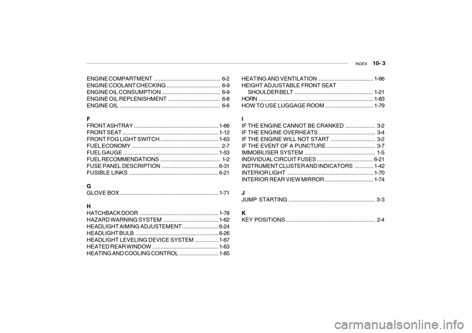
INDEX 10- 3
ENGINE COMPARTMENT . ......................................... 6-2
ENGINE COOLANT CHE CKING.................................. 6-9
ENGINE OIL CONS UMPTION ..................................... 6-9
ENGINE OIL REPLENISHMENT ................................. 6-8
ENGINE OIL ................................................................ 6-6 F FRONT ASHTRAY ...................................................... 1-66
FRONT SEAT ............................................................. 1-12
FRONT FOG LIGHT SWITCH ..................................... 1-63
FUEL ECONO MY ........................................................ 2-7
FUEL GAUGE ............................................................. 1-53
FUEL RECOMMENDATIONS ...................................... 1-2
FUSE PANEL DESCRI PTION .................................... 6-31
FUSIBLE LINKS ......................................................... 6-21
G
GLOVE BOX ............................................................... 1-71
HHATCHBACK DOOR .................................................. 1-78
HAZARD WARNING SYSTEM ................................... 1-62
HEADLIGHT AIMING ADJUSTEMENT.......................6-24
HEADLIGHT BULB ..................................................... 6-26
HEADLIGHT LEVELING DEVICE SYSTEM ...............1-67
HEATED REAR WINDOW .......................................... 1-63
HEATING AND COOLING CONTROL .........................1-85HEATING AND VENTILATION
...................................1-86
HEIGHT ADJUSTABLE FRONT SEAT SHOULDER BELT .................................................. 1-21
HORN ......................................................................... 1-83
HOW TO USE LUGGAGE ROOM ............................... 1-79
I
IF THE ENGINE CANNOT BE CRANKED ................... 3-2
IF THE ENGINE OVERHEATS .................................... 3-4
IF THE ENGINE WILL NOT START ............................ 3-2
IF THE EVENT OF A PUNCTURE ............................... 3-7
IMMOBILISER SYSTEM ............................................. 1-5
INDIVIDUAL CIRCUIT FUSES .................................... 6-21
INSTRUMENT CLUSTER AND INDICATORS............1-42
INTERIOR LIGHT ....................................................... 1-70
INTERIOR REAR VIEW MIRROR ............................... 1-74
JJUMP STARTING ....................................................... 3-3
KKEY POSITI ONS ......................................................... 2-4
Page:
< prev 1-8 9-16 17-24
