2008 Hyundai Azera heating
[x] Cancel search: heatingPage 283 of 345

6
DO-IT-YOURSELF MAINTENANCE
7
!
G050B01A-AATRecommended Engine CoolantUse a high quality ethylene-glycol coolant
in a 50/50 mix with water. The engine
coolant should be compatible with alumi-
num engine parts. Additional corrosion
inhibitors or additives should not be used.
The cooling system must be maintained
with the correct concentration and type of
engine coolant to prevent freezing and
corrosion. Never allow the concentration
of antifreeze to exceed the 60% level or go
below the 35% level, or damage to the
cooling system may result. For proper con-
centration when adding or replacing the
engine coolant, refer to the following table.
Ambient
temperature
°F (°C)
5 (-15)
-13 (-25)
-31 (-35)
-49 (-45)
65%
60%
50%
40% 35%
40%
50%
60%Water Antifreeze
solution Engine Coolant concentration
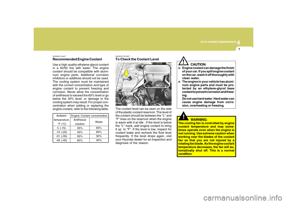
G050C01TG-GATTo Check the Coolant LevelThe coolant level can be seen on the side
of the plastic coolant reservoir. The level of
the coolant should be between the "L" and
"F" lines on the reservoir when the engine
is warm with it at idle . If the level is below
the "L" mark, add engine coolant to bring
it up to "F". If the level is low, inspect for
coolant leaks and recheck the fluid level
frequently. If the level drops again, visit
your Hyundai dealer for an inspection and
diagnosis of the reason.
G050C01TG
!
CAUTION:
o Engine coolant can damage the finish
of your car. If you spill engine coolant
on the car, wash it off thoroughly with
clean water.
o The engine in your vehicle has alumi-
num engine parts and must be pro-
tected by an ethylene-glycol base
coolant to prevent corrosion and freez-
ing.
Do not use hard water. Hard water can
cause engine damage from corro-
sion, overheating or freezing.
WARNING:
The cooling fan is controlled by engine
coolant temperature and may some-
times operate even when the engine is
not running. Use extreme caution when
working near the blades of the coolant
fan so that you are not injured by a
rotating fan blade. As the engine coolant
temperature decreases, the fan will au-
tomatically shut off. This is a normal
condition.
Page 296 of 345

6
DO-IT-YOURSELF MAINTENANCE
20
!
CAUTION:
An open fuse indicates that there is a
problem in the electrical circuit. If you
replace a fuse and it blows as soon as the
accessory is turned on, the problem is
serious and should be referred to a
Hyundai dealer for diagnosis and repair.
Never replace a fuse with anything ex-
cept a fuse with the same or a lower
amperage rating. A higher capacity fuse
could cause damage and create a fire
hazard.NOTE:See page 6-33 for the fuse panel descrip-
tions.
G200C01CM-GATPower ConnectorNOTE:
o If the power connector is pulled up
from the fuse panel, the warning chime,
audio, clock and interior lamps, etc.,
will not operate. The following items
must be reset after replacement.
- Digital Clock
- Trip computer
- Automatic heating and cooling con-
trol system
- Audio
o Even though the power connector is
pulled up, the battery can still be dis-
charged by operation of the head-
lights or other electrical devices.
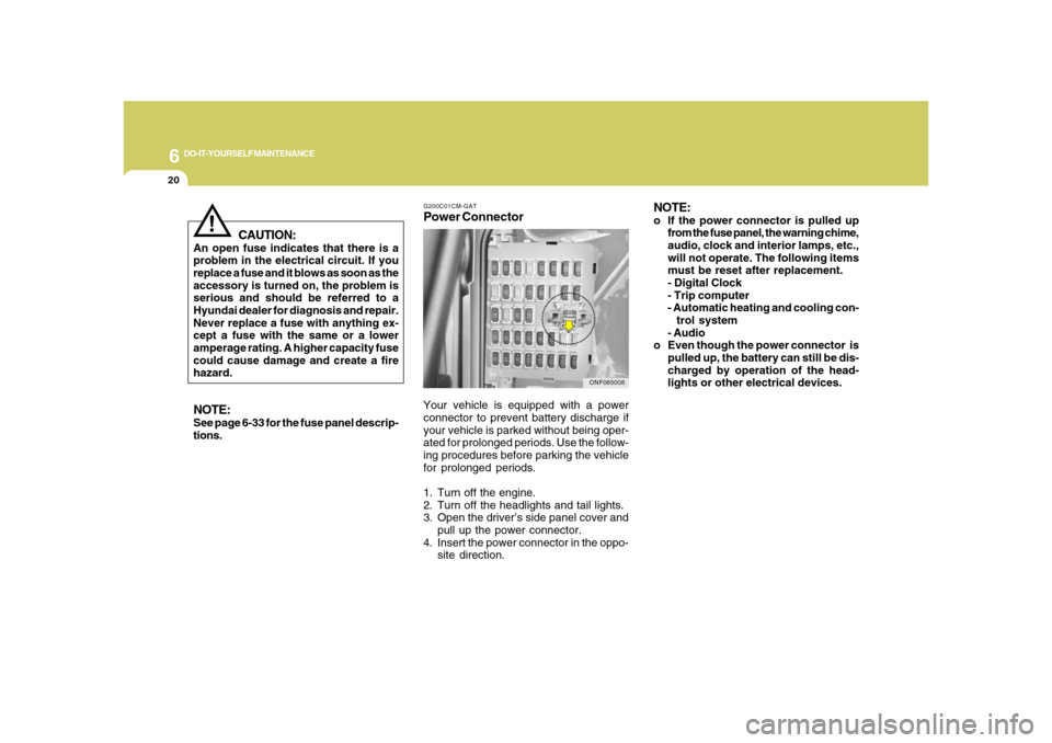
Your vehicle is equipped with a power
connector to prevent battery discharge if
your vehicle is parked without being oper-
ated for prolonged periods. Use the follow-
ing procedures before parking the vehicle
for prolonged periods.
1. Turn off the engine.
2. Turn off the headlights and tail lights.
3. Open the driver’s side panel cover and
pull up the power connector.
4. Insert the power connector in the oppo-
site direction.
ONF065008
Page 339 of 345

10
INDEX
2
A
Accessory Box ....................................................................1-98
Advanced Supplemental Restraint (AIRBAG)
System (SRS) ....................................................................1-43
Curtain airbag .................................................................1-56
Driver's and passenger's front airbag ............................1-44
Occupant classification system ......................................1-51
Side impact airbag .........................................................1-55
Air Cleaner Filter .................................................................. 6-8
Air Conditioning
Care.................................................................................6-16
Operation............................................................ 1-126, 6-16
Switch............................................................................1-128
Antenna ............................................................................1-198
Ashtray................................................................................1-89
Audio System ...................................................................1-137
Audio remote control switch .........................................1-122
Automatic Heating and Cooling Control System ............1-125
Automatic-Dimming Mirror with Z-Nav™ Electronic Compass
Display and HomeLink
®
..................................................................................
1-102
B
Battery .................................................................................6-21
Binding Arbitration .............................................................8-17Brake
Anti-lock brake system (ABS) .........................................2-11
Checking the brakes ......................................................6-14
Fluid.................................................................................6-14
Practices..........................................................................2-14
Breaking-In your New Hyundai ........................................... 1-3
C
Care of Cassette Tapes ...................................................1-196
Care of Discs ....................................................................1-196
Catalytic Converter ............................................................... 7-3
Child Restraint System ......................................................1-34
Installing a child restraint system with
"Tether Anchorage" system ...........................................1-36
Securing a child restraint system with "ISOFIX" system1-37
Child-Protector Rear Door Lock .......................................... 1-9
Cigarette Lighter ................................................................1-88
Climate Control Air Filter ....................................... 1-134, 6-16
Clock...................................................................................1-88
Combination Light ..............................................................1-80
Auto Light ........................................................................1-81
Headlight flasher ............................................................1-82
Headlight switch .............................................................1-80
High-beam switch ...........................................................1-82
Lane change signal ........................................................1-80
Parking light auto off ......................................................1-81
Turn signal operation .....................................................1-80
Page 341 of 345

10
INDEX
4
Fuel Filler Lid
Remote release ............................................................1-112
Fuse Panel Description .....................................................6-33
Fuses..................................................................................6-18
G
General Checks ................................................................... 6-3
Glove Box ...........................................................................1-97
H
Hazard Warning System ....................................................1-87
Headlight
Replacement...................................................................6-25
Switch..............................................................................1-80
Heating and Cooling Control ..........................................1-123
Air flow control ............................................................. 1-130
Air intake control switch ...............................................1-128
Defrosting/Defogging....................................................1-133
Dual temperature control ..............................................1-129
Fan speed control switch .............................................1-127
High-Mounted Rear Stop Light .......................................1-112
Homelink Mirror ................................................................1-102
Hood Release ..................................................................1-114
Horn..................................................................................1-117I
Ignition Switch ...................................................................... 2-4
Immobilizer System .............................................................. 1-3
Instrument Cluster and Indicator Lights ............................1-60
Instrument Panel Light Control (Rheostat) .......................1-88
Integrated Memory System ................................................1-22
Interior Light .......................................................................1-95
J
Jump Starting ....................................................................... 3-3
K
Key ........................................................................................ 1-4
If you lose your keys ......................................................3-18
Positions............................................................................ 2-4
L
Light Bulb Wattage .............................................................6-32
Light Bulbs Replacement ..................................................6-24
Lubrication Chart .................................................................. 9-4
Luggage Net ....................................................................1-111
M
Maintenance Intervals .......................................................... 5-2
Explanation of scheduled maintenance items ................ 5-7
Maintenance under severe usage conditions ................. 5-6