2008 FORD SUPER DUTY brake
[x] Cancel search: brakePage 5 of 25

Familiarize yourself with the winch and each of its components:
1.Motor:Typically powered by vehicle’s battery. Provides power to the
gear mechanism which turns the drum to wind the wire rope.
2.Winch drum:Driven by the motor and drive train. Drum direction can
be changed by using the remote control.
3.Wire rope:Wrapped around the winch drum and fairlead, the wire
rope is looped off at the end to accept the hook’s clevis pin. When the
rope is being reeled in under motor power, it is being “powered in”.
When the wire rope is being reeled out under motor power, it is being
“powered out”. “Powering out” is different than “freespooling out” which
refers to the wire rope being pulled out by hand with the clutch
disengaged.
4.Fairlead:Acts as a guide for the wire rope when using the winch at
an angle. Minimizes damage to the wire rope while it goes through the
winch mount or bumper.
5.Gear train:Converts winch motor power into pulling force.
6.Braking system:Prevents winch from paying out line, which in turn
holds the vehicle in place. The brake is automatically applied to the
winch drum when the motor is stopped and there is load on the rope.
2008 F-250/350/450/550(f23)
Supplement
USA(fus)
Driver Controls
5
Page 9 of 25
becomes the anchor point. In this case, be sure to put the transmission
in neutral, apply the parking brake and block the wheels to prevent it
from moving.
The anchor point should allow you to pull straight in the direction the
vehicle will move. This allows the rope to wind tightly and evenly on the
winch drum. An anchor point as far away as possible will provide the
winch with its greatest pulling power.
Winching hand signals
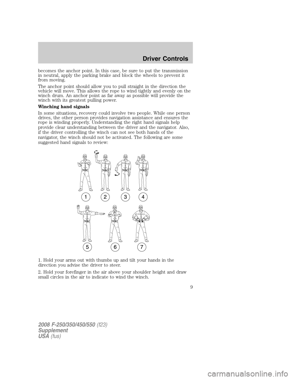
In some situations, recovery could involve two people. While one person
drives, the other person provides navigation assistance and ensures the
rope is winding properly. Understanding the right hand signals help
provide clear understanding between the driver and the navigator. Also,
if the driver controlling the winch can not see both hands of the
navigator, the winch should not be activated. The following are some
suggested hand signals to review:
1. Hold your arms out with thumbs up and tilt your hands in the
direction you advise the driver to steer.
2. Hold your forefinger in the air above your shoulder height and draw
small circles in the air to indicate to wind the winch.
2008 F-250/350/450/550(f23)
Supplement
USA(fus)
Driver Controls
9
Page 10 of 25
3. Point your forefinger down and draw circles in the air about waist
height to indicate feeding more wire from the winch.
4. Tells the driver to wind the winch in short, quick bursts. Open and
close the two fingertips until you want the winch to stop.
5. To signal to stop the winch, clench fist, palm to driver, held high
enough for the driver to see and other arm straight out at shoulder
height.
6. Cross palms together to tell the driver to apply the foot brake.
7. Tells driver to give the tires more drive force to assist the winch
process.
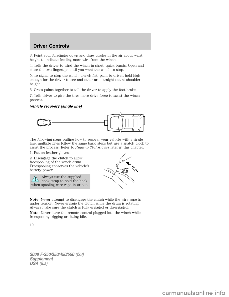
Vehicle recovery (single line)
The following steps outline how to recover your vehicle with a single
line; multiple lines follow the same basic steps but use a snatch block to
assist the process. Refer toRigging Techniqueslater in this chapter.
1. Put on leather gloves.
2. Disengage the clutch to allow
freespooling of the winch drum.
Freespooling conserves the vehicle’s
battery power.
Always use the supplied
hook strap to hold the hook
when spooling wire rope in or out.
Note:Never attempt to disengage the clutch while the wire rope is
under tension. Never engage the clutch while the drum is rotating.
Always make sure the clutch is fully engaged or disengaged.
Note:Never leave the remote control plugged into the winch while
freespooling, rigging or sitting idle.
2008 F-250/350/450/550(f23)
Supplement
USA(fus)
Driver Controls
10
Page 13 of 25
rope slack. During side pulls, the wire rope tends to stack up at one end
of the drum. This stack can become large enough to cause serious
damage to the winch. Line up pulls as straight as possible and stop
winching if the wire rope comes close to the tie rods or mounting plate.
Note:To fix an uneven stack, spool out that section of the rope and
reposition it to the opposite end of the drum; this will free up space for
continued winching.
15. For vehicle recovery, continue pulling until the vehicle is on stable
ground. If the vehicle is able to be driven, the winching operation is
complete.
16. Once recovery of the vehicle is complete, be sure to secure the
vehicle’s brakes and put the transmission in P (Park) (automatic
transmission) or 1 (First) (manual transmission). Release tension in the
wire rope.
17. Disconnect the wire rope from the anchor.
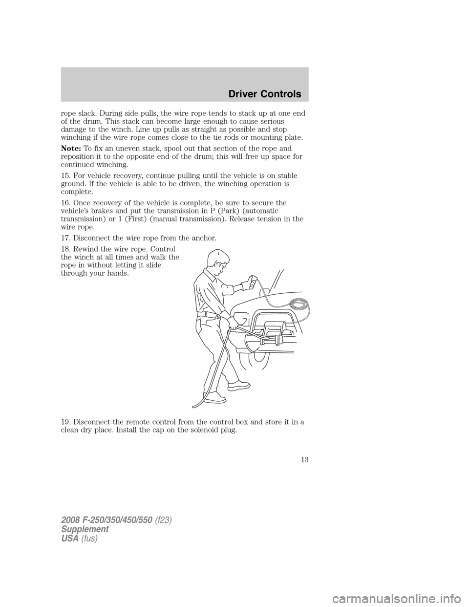
18. Rewind the wire rope. Control
the winch at all times and walk the
rope in without letting it slide
through your hands.
19. Disconnect the remote control from the control box and store it in a
clean dry place. Install the cap on the solenoid plug.
2008 F-250/350/450/550(f23)
Supplement
USA(fus)
Driver Controls
13
Page 18 of 25
ANTI-LOCK BRAKE SYSTEM (ABS) DEACTIVATION IN 4WD
(IF EQUIPPED)
Refer to the label on the back of the sun visor mirror regarding Anti-lock
Brake System (ABS) operation.
Your vehicle’s Anti-lock Brake System (ABS) may be designed to
deactivate when 4WD Low is engaged. The ABS indicator (
ABS)
illuminates and stays on, to indicate that ABS is deactivated, as long as
4WD Low is engaged.
When 4WD Low is disengaged, the ABS light turns off and the system is
active again.
SUSPENSION UPGRADE PACKAGE
Your vehicle is equipped with a special suspension package that will
enhance the vehicle’s off-road performance. The vehicle will handle
differently, both on and off-road, from a factory-equipped passenger car
or truck.
Vehicles with a higher center of gravity such as utility and
four-wheel drive vehicles handle differently than vehicles with a
lower center of gravity. Utility and four-wheel drive vehicles are not
designed for cornering at speeds as high as passenger cars any more
than low-slung sports cars are designed to perform satisfactorily under
off-road conditions. Avoid sharp turns, excessive speed and abrupt
maneuvers in these vehicles. Failure to drive cautiously could result in
an increased risk of loss of vehicle control, vehicle rollover, personal
injury and death.
If the vehicle is not equipped with in-cab suspension controls, the shock
settings are preset and not adjustable inside the vehicle. Contact your
authorized technician to make any necessary adjustments. Maximum
pressure is 15 psi for off-road operation with maximum load.
2008 F-250/350/450/550(f23)
Supplement
USA(fus)
Driving
18
Page 20 of 25
LIMITED SLIP FRONT DIFFERENTIAL/LOCKING REAR
DIFFERENTIAL (IF EQUIPPED)
General information
Your vehicle may be equipped with a limited slip front differential and a
locking rear differential; vehicles equipped with these differentials should
be identified on the Safety Certification Label on the B-pillar or the edge
of the driver’s door. Vehicle handling characteristics will be different than
a conventional differential. Examples of this would be:
•When turning a corner, the sound of component disengagement and
re-engagement may be audible, and the transfer of driving torque from
both wheels to one wheel may be noticeable.
•When going from drive (acceleration) to coast (deceleration) in a
turn, a “metallic” sound may be heard as torque flow is reversed
(inside wheel engaged during acceleration; outside wheel engaged
during deceleration).
•When negotiating a turn (outside wheel disengaged), the inside wheel
under conditions of poor traction may receive excessive torque, which
could cause it to break traction momentarily until its speed is equal to
the outside wheel. This will result in re-engagement of the outside
wheel thus allowing both wheels to be driven. This condition is most
noticeable with lightly loaded axles.
Use extreme caution when accelerating or decelerating on
slippery or unstable surfaces. Vehicles/axles equipped with
traction differentials are inherently more sensitive to side-slip than
vehicles equipped with conventional differentials. Stability can be
retained if side-slip occurs by decelerating (letting off the accelerator).
Do not apply the brake. To do so may result in loss of vehicle control.
The vehicle’s braking capacity is reduced when a turn is made while
coasting downhill because the inside wheel is then disconnected from the
driveline. Operating in low gear will allow the engine to act as a retarder
and will improve braking capacity.
2008 F-250/350/450/550(f23)
Supplement
USA(fus)
Driving
20
Page 21 of 25
Inspection and lubrication
When servicing any driveline components on a vehicle equipped
with a locking rear differential, ensure that the engine is off and
all wheels are off the ground to prevent the vehicle from moving. Axles
equipped with a locking rear differential deliver power to both wheels,
even when only one wheel is on the ground. Failure to observe these
cautionary measures may cause the vehicle to move which can result
in property damage, personal injury, even death.
This differential is designed to operate in the lubricant recommended by
the vehicle/axle manufacturer; no special lubricant is needed. Refer to
theMaintenance Product Specifications and Capacitiesin your
Owner’s Guidefor the proper axle lubricant. For very cold weather
applications, use the lightest oil the axle manufacturer will allow to
overcome possible sluggish re-engagement of the driven clutch
assemblies.
No adjustments or alterations should be made to the differential. Refer to
the vehicle/axle manufacturer’s instructions for adjustments to other
components in the axle.
SAND INGESTION
When driving through sand, traction or brake capability may be limited.
Also, sand may enter your engine’s air intake and severely damage your
engine or your vehicle may stall. Driving through sand where the
transmission vent tube or external breather kit is submerged may allow
sand into the transmission and cause internal transmission damage.
2008 F-250/350/450/550(f23)
Supplement
USA(fus)
Driving
21