Page 169 of 280

STARTING
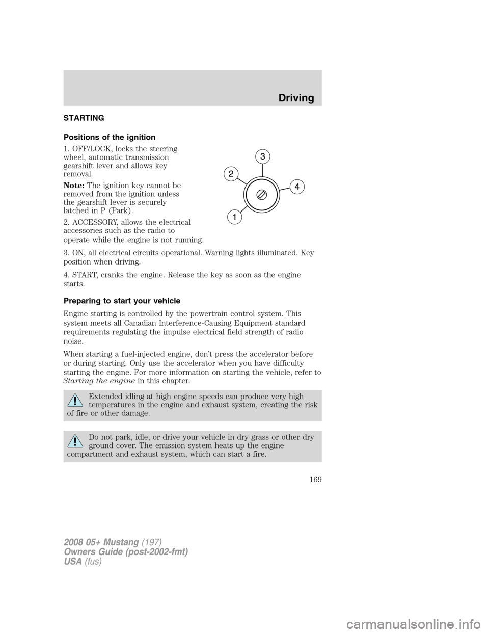
Positions of the ignition
1. OFF/LOCK, locks the steering
wheel, automatic transmission
gearshift lever and allows key
removal.
Note:The ignition key cannot be
removed from the ignition unless
the gearshift lever is securely
latched in P (Park).
2. ACCESSORY, allows the electrical
accessories such as the radio to
operate while the engine is not running.
3. ON, all electrical circuits operational. Warning lights illuminated. Key
position when driving.
4. START, cranks the engine. Release the key as soon as the engine
starts.
Preparing to start your vehicle
Engine starting is controlled by the powertrain control system. This
system meets all Canadian Interference-Causing Equipment standard
requirements regulating the impulse electrical field strength of radio
noise.
When starting a fuel-injected engine, don’t press the accelerator before
or during starting. Only use the accelerator when you have difficulty
starting the engine. For more information on starting the vehicle, refer to
Starting the enginein this chapter.
Extended idling at high engine speeds can produce very high
temperatures in the engine and exhaust system, creating the risk
of fire or other damage.
Do not park, idle, or drive your vehicle in dry grass or other dry
ground cover. The emission system heats up the engine
compartment and exhaust system, which can start a fire.
2008 05+ Mustang(197)
Owners Guide (post-2002-fmt)
USA(fus)
Driving
169
Page 177 of 280

The Traction Control™ system will allow your vehicle to make better use
of available traction on slippery surfaces while you are trying to
accelerate or while your foot is on the accelerator pedal. The system is a
driver aid which makes your vehicle easier to handle primarily on snow
and ice covered roads.
During Traction Control™ operation,
the traction control active light will
illuminate. If your vehicle is
equipped with a message center, a
message will display during Traction
Control™ operation. You may hear
an electric motor type of sound coming from the engine compartment
and the engine will not “rev-up” when you push further on the
accelerator. This is normal system behavior and should be no reason for
concern.
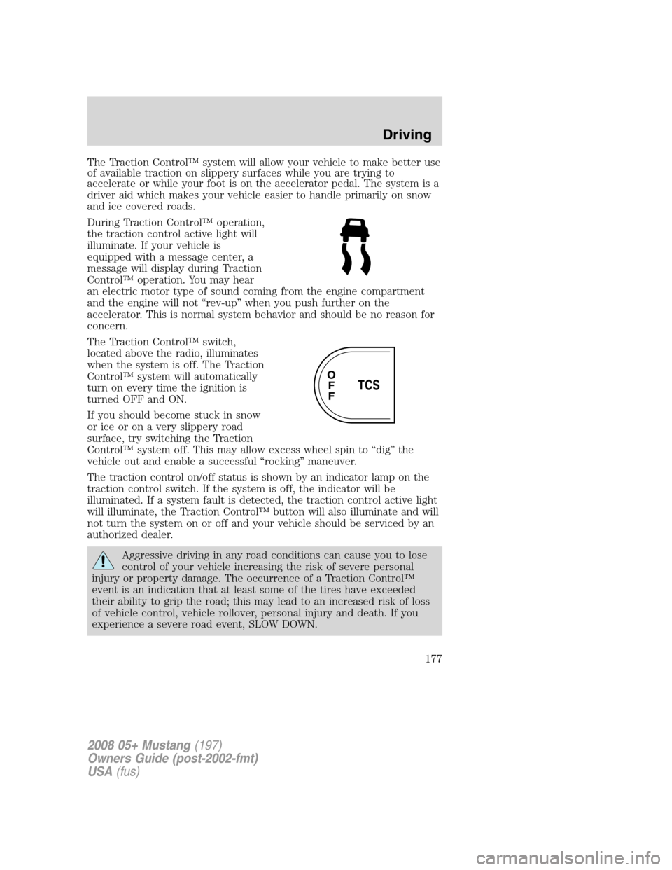
The Traction Control™ switch,
located above the radio, illuminates
when the system is off. The Traction
Control™ system will automatically
turn on every time the ignition is
turned OFF and ON.
If you should become stuck in snow
or ice or on a very slippery road
surface, try switching the Traction
Control™ system off. This may allow excess wheel spin to “dig” the
vehicle out and enable a successful “rocking” maneuver.
The traction control on/off status is shown by an indicator lamp on the
traction control switch. If the system is off, the indicator will be
illuminated. If a system fault is detected, the traction control active light
will illuminate, the Traction Control™ button will also illuminate and will
not turn the system on or off and your vehicle should be serviced by an
authorized dealer.
Aggressive driving in any road conditions can cause you to lose
control of your vehicle increasing the risk of severe personal
injury or property damage. The occurrence of a Traction Control™
event is an indication that at least some of the tires have exceeded
their ability to grip the road; this may lead to an increased risk of loss
of vehicle control, vehicle rollover, personal injury and death. If you
experience a severe road event, SLOW DOWN.
2008 05+ Mustang(197)
Owners Guide (post-2002-fmt)
USA(fus)
Driving
177
Page 180 of 280

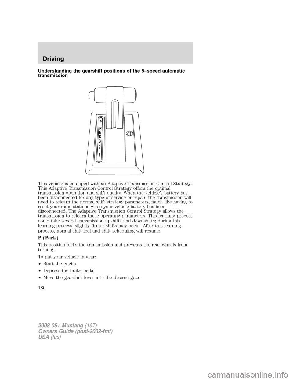
Understanding the gearshift positions of the 5–speed automatic
transmission
This vehicle is equipped with an Adaptive Transmission Control Strategy.
This Adaptive Transmission Control Strategy offers the optimal
transmission operation and shift quality. When the vehicle’s battery has
been disconnected for any type of service or repair, the transmission will
need to relearn the normal shift strategy parameters, much like having to
reset your radio stations when your vehicle battery has been
disconnected. The Adaptive Transmission Control Strategy allows the
transmission to relearn these operating parameters. This learning process
could take several transmission upshifts and downshifts; during this
learning process, slightly firmer shifts may occur. After this learning
process, normal shift feel and shift scheduling will resume.
P (Park)
This position locks the transmission and prevents the rear wheels from
turning.
To put your vehicle in gear:
•Start the engine
•Depress the brake pedal
•Move the gearshift lever into the desired gear
2008 05+ Mustang(197)
Owners Guide (post-2002-fmt)
USA(fus)
Driving
180
Page 188 of 280

HAZARD FLASHER CONTROL
The hazard flasher is located on the
instrument panel by the radio. The
hazard flashers will operate when
the ignition is in any position or if
the key is not in the ignition.
Push in the flasher control and all
front and rear direction signals will flash. Press the flasher control again
to turn them off. Use it when your vehicle is disabled and is creating a
safety hazard for other motorists.
Note:With extended use, the flasher may run down your battery.
FUEL PUMP SHUT-OFF SWITCH
FUEL
RESET
This device stops the electric fuel pump from sending fuel to the engine
when your vehicle has had a substantial jolt.
After an accident, if the engine cranks but does not start, this switch
may have been activated.
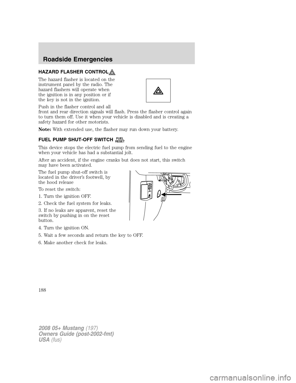
The fuel pump shut-off switch is
located in the driver’s footwell, by
the hood release
To reset the switch:
1. Turn the ignition OFF.
2. Check the fuel system for leaks.
3. If no leaks are apparent, reset the
switch by pushing in on the reset
button.
4. Turn the ignition ON.
5. Wait a few seconds and return the key to OFF.
6. Make another check for leaks.
2008 05+ Mustang(197)
Owners Guide (post-2002-fmt)
USA(fus)
Roadside Emergencies
188
Page 191 of 280

Fuse/Relay
LocationFuse Amp
RatingPassenger Compartment Fuse
Panel Description
13 — Not used
14 5A A/C cycle switch
15 10A Brake On/Off (BOO) power
16 5A Cluster
17 10A Restraint Control Module (RCM),
Passenger Occupant Detection
System (PODS), Passenger Air
bag Deactivation Indicator (PADI)
18 10A Anti-lock Brake System (ABS)
19 5A Powertrain Control Module (PCM)
relay, Passive Anti-Theft System
(PATS), Instrument cluster airbag
warning lamp
20 10A Radio (Start)
21 10A Starter relay
Power distribution box
The power distribution box is located in the engine compartment. The
power distribution box contains high-current fuses that protect your
vehicle’s main electrical systems from overloads.
Do not probe the contacts for the fuses and relays in the power
distribution box as damage will occur, causing improper, or loss
of, electrical functionality.
Always disconnect the battery before servicing high current
fuses.
To reduce risk of electrical shock, always replace the cover to
the Power Distribution Box before reconnecting the battery or
refilling fluid reservoirs.
If the battery has been disconnected and reconnected, refer to the
Batterysection of theMaintenance and Specificationschapter.
2008 05+ Mustang(197)
Owners Guide (post-2002-fmt)
USA(fus)
Roadside Emergencies
191
Page 192 of 280
The high-current fuses are coded as follows.
Fuse/Relay
LocationFuse Amp
RatingPower Distribution Box
Description
1 — Not used
2 30A* Climate control blower
3 40A* Cooling fan
4 30A* Starter
5 30A* Driver front window motor
6 30A* Rear amplifier (Shaker 1000
radio)
7 30A* Passenger front window motor
8 40A* Anti-lock Brake System (ABS) #1
9 30A* Rear amplifier (Shaker 1000
radio)
10 30A* Wipers
11 30A* Driver rear window motor
(Convertible only)
12 30A* Passenger rear window motor
(Convertible only)
13 40A* Convertible top
2008 05+ Mustang(197)
Owners Guide (post-2002-fmt)
USA(fus)
Roadside Emergencies
192
Page 193 of 280
Fuse/Relay
LocationFuse Amp
RatingPower Distribution Box
Description
14 30A* Driver seat
15 30A* Passenger seat
16 30A* Front amplifier (Shaker 500
radio)
20 Mini relay PCM
21 Micro relay Fuel pump
22 Micro relay Starter
23 — Not used
24 Micro relay A/C clutch
25 Mini relay Cooling fan (High-speed)
26 Micro relay Horn
27 Micro relay High beams
28 Mini relay Cooling fan (Low-speed)
29 Mini relay Rear defroster
30 Micro relay Fog lamps
31 Mini relay Convertible top (Up)
32 Mini relay Climate control blower
33 Mini relay Convertible top (Down)
34 Micro relay Decklid
39 15A** Engine #4
40 15A** Engine #2
41 15A** Fuel pump
42 15A** Engine #3
43 10A** Alternator
44 10A** Delayed accessory
45 10A** PCM
46 25A** Horn
47 15A** Engine #1
48 Diode A/C clutch
49 15A** A/C clutch
50 15A** High beams
2008 05+ Mustang(197)
Owners Guide (post-2002-fmt)
USA(fus)
Roadside Emergencies
193
Page 194 of 280
Fuse/Relay
LocationFuse Amp
RatingPower Distribution Box
Description
51 10A** Convertible top
52 30A** Rear defroster
53 Diode PCM
54 20A** Left HID headlamp
55 20A** Right HID headlamp
56 20A** Radio, SDARS
57 20A** Decklid release
58 15A** Fog lamps
59 30A** SJB #5 (Passenger compartment
fuse box)
60 — Not used
61 20A** Power point #1 (Instrument
panel)
62 20A** SJB #7 (Passenger compartment
fuse box)
63 30A** SJB #6 (Passenger compartment
fuse box)
64 20A** Power point #2 (Console)
65 30A** ABS #2
66 25A** Heated seats
67 30A** SJB #4 (Passenger compartment
fuse box)
68 20A** Ignition
* Cartridge Fuses ** Mini Fuses
2008 05+ Mustang(197)
Owners Guide (post-2002-fmt)
USA(fus)
Roadside Emergencies
194