Page 133 of 273

Before hook-up, make sure:
•The fifth wheel jaws are fully opened.
•The fifth wheel is fully tilted back to prevent body damage when the
tractor is backed under a trailer.
•The trailer wheels are blocked and the trailer spring brakes are
adjusted and applied. Never chase a trailer.
•The brake hoses and light cords are clear of the fifth wheel.
Hook-up
1. Back the tractor squarely under the trailer, engaging the fifth wheel
jaws on the kingpin. Always back-up slowly, making sure the trailer is
neither too high nor too low. Avoid backing under the trailer from an
angle.
2. Connect the service and emergency brake hoses and trailer light
connector. Refer toTractor-trailer connectionin theAir suspension
section of this chapter, adhering to the warning and using the three-point
stance while connecting and disconnecting the trailer.
3. Inspect the jaws of the fifth wheel to be sure they have fully closed on
the trailer kingpin and the trailer plate is resting securely on the fifth
wheel.
4. Be sure the coupler release lever is in the locked position.
5. Charge the trailer brake system. Set the trailer brakes, either with the
hand valve or tractor protection valve. Pull against the trailer for an
additional check of proper hook-up. Do not pull hard enough to damage
or strain the equipment.
6. Set the tractor parking brakes and fully raise the trailer landing gear.
Refer toBrakesin this chapter for proper operation of the parking brake
and trailer brakes.
7. Check the operation of all trailer lights and correct any lights that may
be faulty.
Un-hook
1. Try to keep the tractor and trailer in a straight line.
2. Apply the parking brakes.
3. Lower the trailer landing gear, making sure it is on solid, level ground.
The weight of the trailer is to be on the landing gear.
4. Block the trailer wheels.
2008 F-650/750(f67)
Supplement
USA(fus)
Driving
132
Page 134 of 273
5. Disconnect the brake hoses and light cords. Be sure hoses and cords
are clear.
6. Pull coupler release lever to disengage the fifth wheel jaws.
7. Release the tractor parking brakes.
8. Pull out from the trailer slowly, allowing the landing gear to take the
load gradually.
2008 F-650/750(f67)
Supplement
USA(fus)
Driving
133
Page 137 of 273
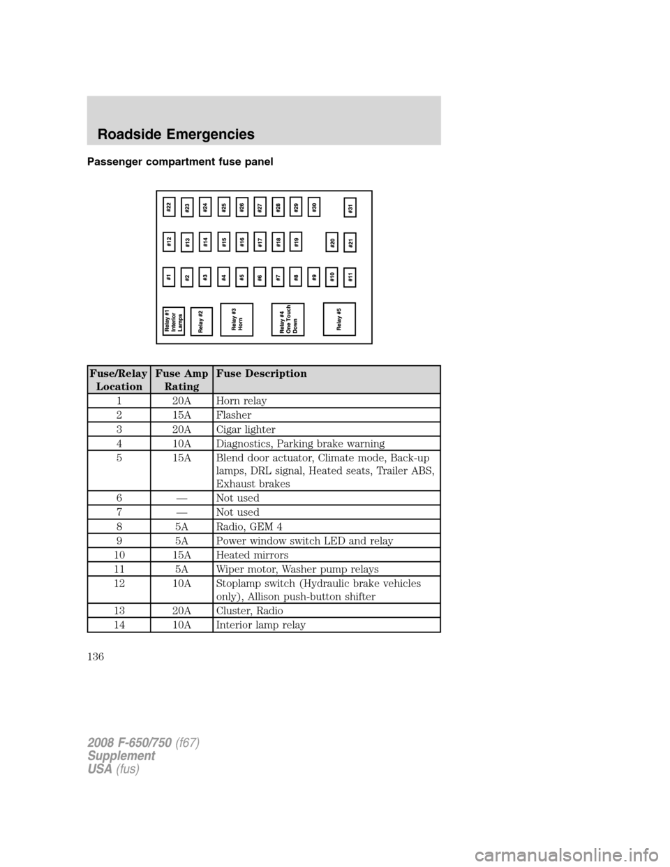
Passenger compartment fuse panel
Fuse/Relay
LocationFuse Amp
RatingFuse Description
1 20A Horn relay
2 15A Flasher
3 20A Cigar lighter
4 10A Diagnostics, Parking brake warning
5 15A Blend door actuator, Climate mode, Back-up
lamps, DRL signal, Heated seats, Trailer ABS,
Exhaust brakes
6 — Not used
7 — Not used
8 5A Radio, GEM 4
9 5A Power window switch LED and relay
10 15A Heated mirrors
11 5A Wiper motor, Washer pump relays
12 10A Stoplamp switch (Hydraulic brake vehicles
only), Allison push-button shifter
13 20A Cluster, Radio
14 10A Interior lamp relay
2008 F-650/750(f67)
Supplement
USA(fus)
Roadside Emergencies
136
Page 139 of 273
To reduce risk of electrical shock, always replace the cover to
the Power Distribution Box before reconnecting the battery or
refilling fluid reservoirs.
Fuse/Relay
LocationFuse Amp
RatingFuse Description
1 15A* Main light switch
2 30A* Power seat (driver)
3 30A* Power seat (passenger)
4 15A* Washer pump relay, Washer pump motor
5 — Not used
6 15A* Air intake heater (Caterpillar engine only)
7 15A* Stoplamp switches (Air brake vehicles only)
8 25A* Fuel heater relay (Caterpillar
engine-equipped vehicles with dual fuel tanks
only)
9 20A* Inhibit relay, Engine ECM, Cluster,
Transmission TCM
10 15A* Heated drain valve
11 30A* Electric trailer brake
2008 F-650/750(f67)
Supplement
USA(fus)
Roadside Emergencies
138
Page 140 of 273

Fuse/Relay
LocationFuse Amp
RatingFuse Description
12 20A* Daytime Running Lamps (DRL), Blend door
actuator, Climate mode, Back-up, Heated
seats, Trailer ABS, Exhaust brake
13 — Not used
14 — Not used
15 7.5A* Body builder - trailer adapter stoplamps
16 5A* Bendix Air ABS (Air brake vehicles only)
WABCO ABS (Hydraulic brake vehicles only)
17 — Not used
18 10A* Fuel transfer pump (duel fuel tanks only)
19 — Not used
20 — Not used
21 10A* Hydromax motor control
22 — Not used
23 — Not used
24 — Not used
101 30A** Bendix Air ABS relay (Air brake vehicles
only)
WABCO ABS modulator relay (Hydraulic
brake vehicles only)
102 20A** Ignition switch to customer access
103 20A** Ignition switch (Junction box fuses 8, 9, 10,
11, 19, 29 and 30)
104 20A** Power point
105 20A** Power door locks
106 30A** Main light switch, Multifunction switch, CJB
fuses 16, 26 and 28, Headlamps, DRL relays
107 50A** Junction box fuses 1, 2, 3, 4, 12, 13, 14 and
15
108 40A** Fuel heater relay (Cummins engine only)
109 40A** Power window relay
110 30A** Wiper power relay (Park, Low/High speed)
2008 F-650/750(f67)
Supplement
USA(fus)
Roadside Emergencies
139
Page 148 of 273

Note:To avoid transmission damage, vehicles should not be towed even
a short distance without suspending rear wheels or removing the axle
shaft or driveshaft.
Note:In the event the chassis is equipped with a tandem axle and the
vehicle is to be towed from the front, the forward rear axle may be
raised to clear the road surface and secured to the frame by chains or
U-bolts, allowing only the rear rear axle to contact the road surface. Axle
shafts must be removed from the rear rear axle assembly. The wheel hub
ends must be covered to prevent loss of axle lubricant and entrance of
contaminants. Use extreme care in securing the chains or U-bolts to
avoid possible damage to the brake lines, hoses or other components.
Towing vehicles equipped with a driver-controlled differential lock
Note:If the vehicle must be towed to a service facility with the drive
axle wheels on the ground, it is necessary to remove the axle shafts
before the vehicle is towed.
1. Shift collar in the locked position
2. Actuator assembly and shift fork
3. Axle shaft
4. Interference between the shift
collar and housing
5. Shift collar in the unlocked
position
6. Outer splines - axle shaft to collar
7. Shift collar and differential case
splines
8. Inner splines - axle shaft to side
gear
9. Side gear
10. Differential (plain) case half
Removing axle shafts before towing
1. Shift the main differential to the unlocked (disengaged) position. The
differential lock light will turn off.
2008 F-650/750(f67)
Supplement
USA(fus)
Roadside Emergencies
147
Page 185 of 273

When these steps are performed successfully in the order outlined above,
the DPF lamp will begin flashing at a rate of once every 10 seconds. The
engine speed may also increase slightly. To allow parked regeneration to
continue uninterrupted:
1. The vehicle must remain parked
2. The transmission must remain in P (Park) or N (Neutral) (as
previously described in Step 2).
3. The accelerator pedal, service brake pedal, and clutch pedal (if
equipped) must not be depressed
4. The parking brake must remain set
On average (depending on filter level and other factors), the process will
take 20–30 minutes to complete. The DPF lamp will turn off when the
process is complete. Repeat Steps 1–5, if parked regeneration is
interrupted.
To discontinue parked regeneration (Cummins engine only)
Depress any of the floor pedals to discontinue parked regeneration.
Diesel particulate filter maintenance and service
The DPF is designed to retain a relatively large amount of residual ash
and provide many miles and hours of maintenance-free operation. At
some point, generally beyond 150,000 miles (240,000 km) or 5,000 hours
of operation (whichever comes first), the DPF will require professional
cleaning to remove the accumulated ash
The exact number of miles or hours of operation will vary greatly
depending upon vehicle/engine loading and operating conditions, ash
content of the engine oil, and quality of the diesel fuel used in your
truck. Adhering to your engine manufacturer’s recommended oil and fuel
specifications will maximize the miles and hours of operation before a
DPF professional cleaning is required. Refer to your engine
manufacturer’s owner’s manual for more details regarding recommended
maintenance and service of your DPF.
Exhaust outlet assembly
The normal operating temperature of the exhaust system is very
high. Never work around or attempt to repair any part of the
exhaust system until it has cooled. Failure to follow these instructions
may result in personal injury.
2008 F-650/750(f67)
Supplement
USA(fus)
Maintenance and Specifications
184
Page 194 of 273

such as the fuel sender, cranking motor, alternator and feed-through
studs should be cleaned and re-coated with a lubricant sealing grease
such as Motorcraft Silicone Brake Caliper Grease and Dielectic
Compound XG-3, or equivalent. This should include the ground cable
connector for batteries, engine and cab as well as the jump starting stud.
Accessory feed connections
Vehicle electrical systems are complex and often include electronic
components such as engine and transmission controls, instrument panels,
ABS, etc. While most systems operate on battery voltage (12 volts),
some systems can be as high as 90 volts or as low as five volts. Refer to
the Electrical Circuit Diagram Manuals, available from your vehicle’s
manufacturer, to ensure that any additional body lights and accessories
are connected to circuits that are both appropriate and not overloaded.
No modification should be made to any vehicle control system without
first contacting your dealer.
SUSPENSION INSPECTION
Note:Do not adjust air suspension height to any setting other than the
specified setting. Altering the height setting will change the driveline
angle and may result in unwarrantable component damage, such as
transmission component damage.
Verify drive axle air suspension height and height control valve
performance at engine lube oil change intervals.
Periodically:
•Check condition of spring leaves for evidence of fatigue, bending or
breakage.
•Check condition of suspension mounting brackets and bushings.
•Check that torque rod mounting fasteners are tight.
•Check to be sure the suspension alignment is maintained at all times.
•Check U-bolts after the chassis has been operating under load for
1,000 miles (1,600 km) or six months, whichever comes first, the
U-Bolt nuts must be re-torqued. The U-Bolt nuts thereafter must be
re-torqued every 36,000 miles (58,000 km). The U-Bolt and nut
threads and seats should be cleaned and lubricated to ensure a “like
new” condition when re-torquing.
Note:See theU-Bolt Nut Torquechart later in this section.
2008 F-650/750(f67)
Supplement
USA(fus)
Maintenance and Specifications
193