2008 FORD F250 wiring
[x] Cancel search: wiringPage 96 of 400
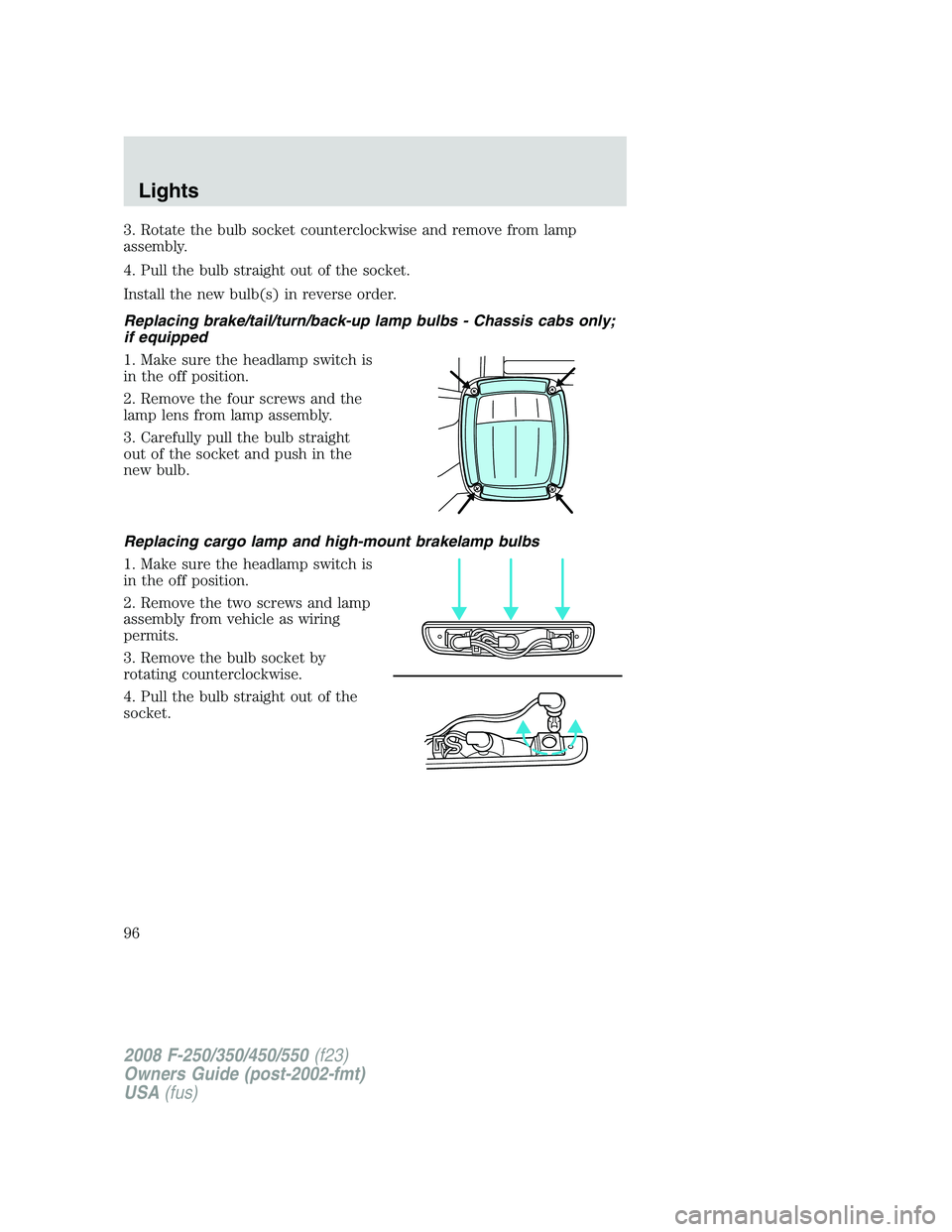
3. Rotate the bulb socket counterclockwise and remove from lamp
assembly.
4. Pull the bulb straight out of the socket.
Install the new bulb(s) in reverse order.
Replacing brake/tail/turn/back-up lamp bulbs - Chassis cabs only;
if equipped
1. Make sure the headlamp switch is
in the off position.
2. Remove the four screws and the
lamp lens from lamp assembly.
3. Carefully pull the bulb straight
out of the socket and push in the
new bulb.
Replacing cargo lamp and high-mount brakelamp bulbs
1. Make sure the headlamp switch is
in the off position.
2. Remove the two screws and lamp
assembly from vehicle as wiring
permits.
3. Remove the bulb socket by
rotating counterclockwise.
4. Pull the bulb straight out of the
socket.
2008 F-250/350/450/550(f23)
Owners Guide (post-2002-fmt)
USA(fus)
Lights
96
Page 141 of 400
1. Before removal of the tailgate, locate and disconnect the electrical
connector under the pick-up box on the right-hand side of the vehicle
near the spare tire.
2. Install the protective cap (tethered to the wiring harness under the
vehicle) on the RCS connector.
3. Carefully bring the wiring harness up between the pick-up box and the
bumper. Secure the tailgate harness onto the pick-up box.
4. Lower the tailgate.
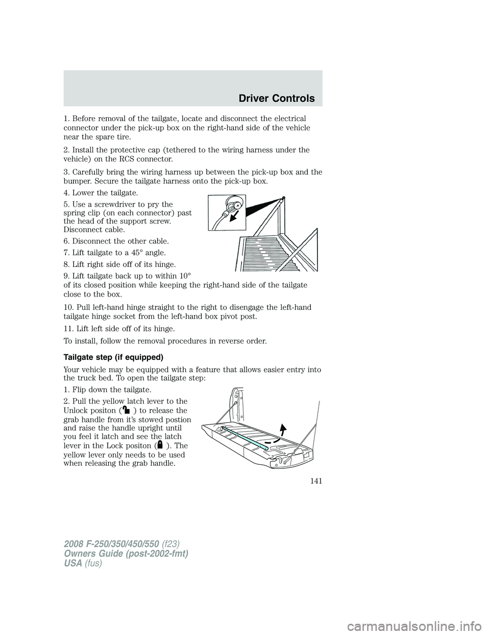
5. Use a screwdriver to pry the
spring clip (on each connector) past
the head of the support screw.
Disconnect cable.
6. Disconnect the other cable.
7. Lift tailgate to a 45° angle.
8. Lift right side off of its hinge.
9. Lift tailgate back up to within 10°
of its closed position while keeping the right-hand side of the tailgate
close to the box.
10. Pull left-hand hinge straight to the right to disengage the left-hand
tailgate hinge socket from the left-hand box pivot post.
11. Lift left side off of its hinge.
To install, follow the removal procedures in reverse order.
Tailgate step (if equipped)
Your vehicle may be equipped with a feature that allows easier entry into
the truck bed. To open the tailgate step:
1. Flip down the tailgate.
2. Pull the yellow latch lever to the
Unlock positon (
) to release the
grab handle from it’s stowed postion
and raise the handle upright until
you feel it latch and see the latch
lever in the Lock positon (
). The
yellow lever only needs to be used
when releasing the grab handle.
2008 F-250/350/450/550(f23)
Owners Guide (post-2002-fmt)
USA(fus)
Driver Controls
141
Page 187 of 400

restrained or are otherwise out of position at the time of airbag
deployment. Thus, it is extremely important that occupants be properly
restrained as far away from the airbag module as possible while
maintaining vehicle control.
Several air bag system components get hot after inflation. Do not
touch them after inflation.
If the air bag has deployed,the air bag will not function
again and must be replaced immediately.If the air bag is not
replaced, the unrepaired area will increase the risk of injury in a
collision.
The SRS consists of:
•driver and passenger airbag modules (which include the inflators and
airbags),
•one or more impact and safing sensors,
•a readiness light and tone
•and the electrical wiring which connects the components.
The diagnostic module monitors its own internal circuits and the
supplemental airbag electrical system wiring (including the impact
sensors), the system wiring, the airbag system readiness light, the airbag
back up power and the airbag ignitors.
Determining if the system is operational
The SRS uses a readiness light in the instrument cluster or a tone to
indicate the condition of the system. Refer toAirbag readinesssection
in theInstrument Clusterchapter. Routine maintenance of the airbag is
not required.
A difficulty with the system is indicated by one or more of the following:
•The readiness light will either
flash or stay lit.
•The readiness light will not
illuminate immediately after
ignition is turned on.
•A series of five beeps will be heard. The tone pattern will repeat
periodically until the problem and/or light are repaired.
If any of these things happen, even intermittently, have the SRS serviced
at your authorized dealer immediately. Unless serviced, the system may
not function properly in the event of a collision.
2008 F-250/350/450/550(f23)
Owners Guide (post-2002-fmt)
USA(fus)
Seating and Safety Restraints
187
Page 235 of 400

Rotation, pressure adjustment
and successful completion of the
TPMS reset procedure
Sensor 1: 80 psi
Sensor 2: 80 psi
Sensor 3: 50 psi
Sensor 4: 50 psi
Tire rotation and air pressure
adjustment followed by sensor
resetting will ensure the system is properly programmed for vehicles
with different front and rear tire pressures and reduce the risk of a false
low tire warning.
In this situation, the TPMS warning light will be off.
SNOW TIRES AND CHAINS
Snow tires must be the same size and grade as the tires you
currently have on your vehicle.
Note:Do not use snow chains on front tires of vehicles with 20” wheels
and tires.
The tires on your vehicle have all weather treads to provide traction in
rain and snow. However, in some climates, you may need to use snow
tires and chains. If you need to use chains, it is recommended that steel
wheels (of the same size and specifications) be used, as chains may chip
aluminum wheels.
Follow these guidelines when using snow tires and chains:
•Use only SAE Class S chains.
•Install chains securely, verifying that the chains do not touch any
wiring, brake lines or fuel lines.
•Drive cautiously. If you hear the chains rub or bang against your
vehicle, stop and re-tighten the chains. If this does not work, remove
the chains to prevent damage to your vehicle.
•If possible, avoid fully loading your vehicle.
•Remove the tire chains when they are no longer needed. Do not use
tire chains on dry roads.
•The suspension insulation and bumpers will help prevent vehicle
damage. Do not remove these components from your vehicle when
using snow tires and chains.
2008 F-250/350/450/550(f23)
Owners Guide (post-2002-fmt)
USA(fus)
Tires, Wheels and Loading
235
Page 249 of 400
6. If the trailer wheels lock-up (indicated by squealing tires), reduce the
GAIN setting; if the trailer wheels turn freely, increase the GAIN setting.
Repeat Steps 5 and 6 until the GAIN setting is at a point just below
trailer wheel lock-up. If towing a heavier trailer, trailer wheel lockup may
not be attainable even with the maximum GAIN setting of 10.
Explanation of instrument cluster messages:
The TBC interacts with the instrument cluster message center. These
messages, accompanied by a single chime, will be displayed when the
TBC determines a malfunction in the trailer connection, TBC system, or
in the trailer. These messages are listed below:
TRAILER DISCONNECTED (if equipped with message center) or
CHECK TRAILER (if equipped with mini message center):This
message is displayed when a trailer connection was determined and then
a disconnection, either intentionally or unintentionally, has been sensed
during a given ignition cycle. It is also displayed if a trailer fault occurs
causing the trailer to appear disconnected. This message is also
displayed during manual activation without a trailer connected.
TBC FAULT:This message is displayed in response to faults sensed by
the TBC. In the event this message is seen, please take your vehicle to
an authorized dealer for diagnosis and repair. The TBC may still function,
but performance may be degraded.
WIRING FAULT ON TRAILER:The TBC is capable of determining
certain faults in the vehicle wiring and trailer wiring/brake system. These
faults do not mean there is anything wrong with the TBC. This message
is displayed when one of the following faults has occurred:
•Short circuit on the electric brake output wire:If the TRAILER
FAULT message is displayed with no trailer connected, the problem is
with the vehicle wiring from the TBC to the 7–pin connector in the
bumper. If the message is only displayed with a trailer connected, the
problem is related to the trailer wiring; consult your trailer dealer for
assistance. This can be a short to ground (i.e., chaffed wire) or a short
to voltage (i.e., pulled pin on trailer emergency break-away battery) or
trailer brakes drawing too much current.
Note:Your TBC can be diagnosed by your authorized dealer to
determine exactly which trailer fault has occurred; however, if the fault
is with the trailer this diagnosis isnotcovered under your Ford
warranty.
Points to Remember:
•Remember to adjust gain setting before using the TBC for the first
time.
2008 F-250/350/450/550(f23)
Owners Guide (post-2002-fmt)
USA(fus)
Tires, Wheels and Loading
249
Page 253 of 400
Backing up
•Practice backing up, particularly if you are a novice. Turn the steering
wheel to the right to move the trailer’s rear end to the right.
•Sharp steering movements may cause the trailer to jackknife or go out
of control.
Tires
•All trailer tires should be of the same size, and construction.
•Select tires that meet the trailer loading requirements.
•Always check tow vehicle and trailer tire pressure before towing.
Launching or retrieving a boat
When backing down a ramp during boat launching or retrieval,
•Do not allow the static water level to rise above the bottom edge of
the rear bumper.
•Do not allow waves to break higher than 6 inches (15 cm) above the
bottom edge of the rear bumper.
•Disconnect the trailer tow electrical connector to prevent blown fuses
caused by water entering into your trailer’s electrical wiring.
Exceeding these limits may allow water to enter critical vehicle
components, adversely affecting driveability, emissions and reliability.
Replace front and rear axle lubricants any time the axles have been
submerged in water. Axle lubricant quantities are not to be checked
unless a leak is suspected.
RECREATIONAL TOWING
Follow these guidelines if you have a need for recreational (RV) towing.
An example of recreational towing would be towing your vehicle behind
a motorhome. These guidelines are designed to ensure that your
transmission is not damaged.
2008 F-250/350/450/550(f23)
Owners Guide (post-2002-fmt)
USA(fus)
Tires, Wheels and Loading
253
Page 391 of 400
Lifestyle
Ash cup / smoker’s package
Bedliners and bedmats
Cargo organization and management
Towing mirrors
Trailer hitches, wiring harnesses and accessories
Peace of mind
Mobile-Ease™ hands-free communication system
Remote start
Vehicle security systems
Wheel locks
Not all accessories are available for all models.
For maximum vehicle performance, keep the following information in
mind when adding accessories or equipment to your vehicle:
•When adding accessories, equipment, passengers and luggage to your
vehicle, do not exceed the total weight capacity of the vehicle or of
the front or rear axle (GVWR or GAWR as indicated on the Safety
Compliance Certification Label). Consult your authorized dealer for
specific weight information.
•The Federal Communications Commission (FCC) and Canadian Radio
Telecommunications Commission (CRTC) regulate the use of mobile
communications systems — such as two-way radios, telephones and
theft alarms - that are equipped with radio transmitters. Any such
equipment installed in your vehicle should comply with FCC or CRTC
regulations and should be installed only by your authorized dealer.
•Mobile communications systems may harm the operation of your
vehicle, particularly if they are not properly designed for automotive
use.
•To avoid interference with other vehicle functions, such as anti-lock
braking systems, amateur radio users who install radios and antennas
onto their vehicle should not locate the Amateur Radio Antennas in
the area of the driver’s side hood.
•Electrical or electronic accessories or components that are added to
the vehicle by the authorized dealer or the owner may adversely affect
battery performance and durability.
2008 F-250/350/450/550(f23)
Owners Guide (post-2002-fmt)
USA(fus)
Accessories
391