2008 FORD F150 fuses
[x] Cancel search: fusesPage 2 of 400
Locks and Security 144
Keys 144
Locks 144
Anti-theft system 155
Seating and Safety Restraints 158
Seating 158
Safety restraints 164
Airbags 183
Child restraints 192
Tires, Wheels and Loading 209
Tire information 211
Tire inflation 213
Tire Pressure Monitoring System (TPMS) 226
Vehicle loading 237
Trailer towing 243
Recreational towing 257
Driving 258
Starting 258
Brakes 264
Traction Control™ 266
Transmission operation 269
Snowplowing 293
Roadside Emergencies 296
Getting roadside assistance 296
Hazard flasher switch 298
Fuel pump shut-off switch 298
Fuses and relays 299
Changing tires 307
Lug nut torque 314
Jump starting 315
Wrecker towing 320
Table of Contents
2
2008 F-150(f12)
Owners Guide (post-2002-fmt)
USA(fus)
Page 108 of 400
AUXILIARY POWER POINT (12VDC)
Power outlets are designed for accessory plugs only. Do not insert
any other object in the power outlet as this will damage the
outlet and blow the fuse. Do not hang any type of accessory or
accessory bracket from the plug. Improper use of the power
outlet can cause damage not covered by your warranty.
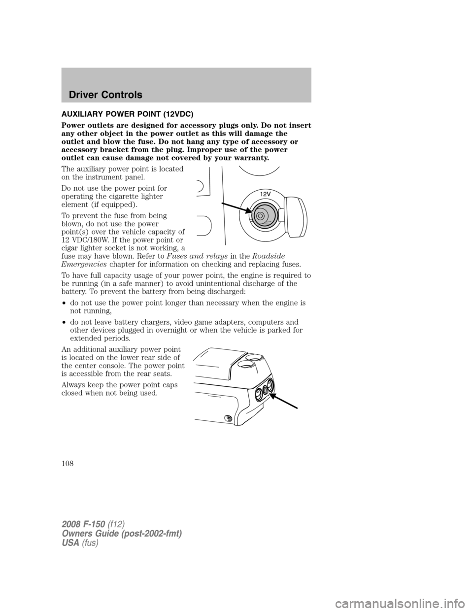
The auxiliary power point is located
on the instrument panel.
Do not use the power point for
operating the cigarette lighter
element (if equipped).
To prevent the fuse from being
blown, do not use the power
point(s) over the vehicle capacity of
12 VDC/180W. If the power point or
cigar lighter socket is not working, a
fuse may have blown. Refer toFuses and relaysin theRoadside
Emergencieschapter for information on checking and replacing fuses.
To have full capacity usage of your power point, the engine is required to
be running (in a safe manner) to avoid unintentional discharge of the
battery. To prevent the battery from being discharged:
•do not use the power point longer than necessary when the engine is
not running,
•do not leave battery chargers, video game adapters, computers and
other devices plugged in overnight or when the vehicle is parked for
extended periods.
An additional auxiliary power point
is located on the lower rear side of
the center console. The power point
is accessible from the rear seats.
Always keep the power point caps
closed when not being used.
2008 F-150(f12)
Owners Guide (post-2002-fmt)
USA(fus)
Driver Controls
108
Page 185 of 400
The National Highway Traffic Safety Administration (NHTSA)
recommends a minimum distance of at least 10 inches (25 cm)
between an occupant’s chest and the driver airbag cover.
Never place your arms or feet over the airbag module as a
deploying airbag can result in serious fractures or other injuries.
To properly position yourself away from the airbag:
•Move your seat to the rear as far as you can while still reaching the
pedals comfortably.
•Recline the seat slightly one or two degrees from the upright position.
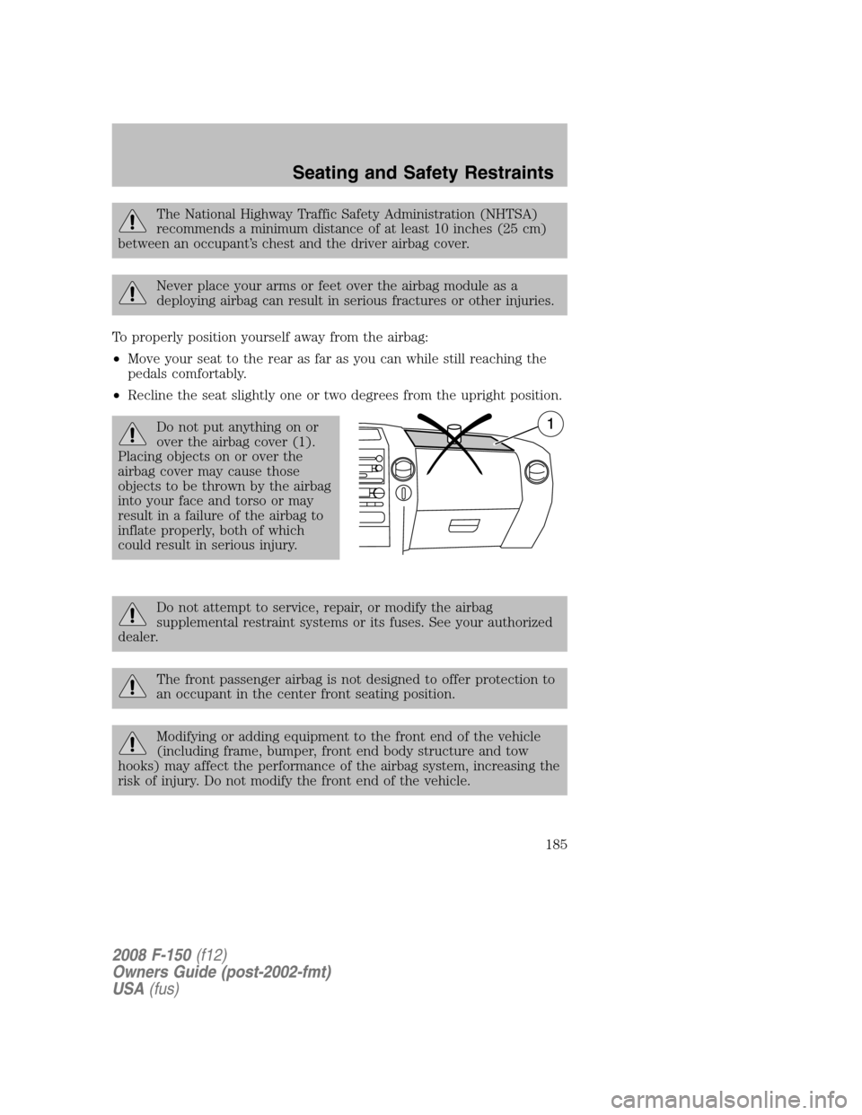
Do not put anything on or
over the airbag cover (1).
Placing objects on or over the
airbag cover may cause those
objects to be thrown by the airbag
into your face and torso or may
result in a failure of the airbag to
inflate properly, both of which
could result in serious injury.
Do not attempt to service, repair, or modify the airbag
supplemental restraint systems or its fuses. See your authorized
dealer.
The front passenger airbag is not designed to offer protection to
an occupant in the center front seating position.
Modifying or adding equipment to the front end of the vehicle
(including frame, bumper, front end body structure and tow
hooks) may affect the performance of the airbag system, increasing the
risk of injury. Do not modify the front end of the vehicle.
2008 F-150(f12)
Owners Guide (post-2002-fmt)
USA(fus)
Seating and Safety Restraints
185
Page 269 of 400
Vehicles with a higher center of gravity such as utility vehicles
and trucks handle differently than vehicles with a lower center
of gravity. Utility vehicles and trucks arenotdesigned for cornering at
speeds as high as passenger cars any more than low-slung sports cars
are designed to perform satisfactorily under off-road conditions. Avoid
sharp turns, excessive speed or abrupt maneuvers in these vehicles.
Failure to drive cautiously could result in an increased risk of loss of
vehicle control, vehicle rollover, personal injury and death.
Loaded vehicles, with a higher center of gravity, may handle
differently than unloaded vehicles. Do not overload your vehicle
and use extra precautions, such as driving at slower speeds, avoiding
abrupt steering changes and allowing for increased stopping distance,
when driving a heavily loaded vehicle. Over-loading or loading the
vehicle improperly can deteriorate handling capability and contribute
to loss of vehicle control and vehicle rollover.
AUTOMATIC TRANSMISSION OPERATION
Brake-shift interlock - column-shift transmission
This vehicle is equipped with a park/brake-shift interlock feature that
prevents the gearshift lever from being moved from P (Park) when the
ignition is in the ON position unless the brake pedal is depressed.
If you cannot move the gearshift lever out of P (Park) with ignition in
the ON position and the brake pedal depressed, it is possible that a fuse
has blown or the vehicle’s brakelamps are not operating properly. Refer
toFuses and relaysin theRoadside Emergencieschapter.
If the fuse is not blown, perform the following procedure:
1. Apply the parking brake, turn the ignition to OFF/LOCK, then remove
the key.
2008 F-150(f12)
Owners Guide (post-2002-fmt)
USA(fus)
Driving
269
Page 270 of 400
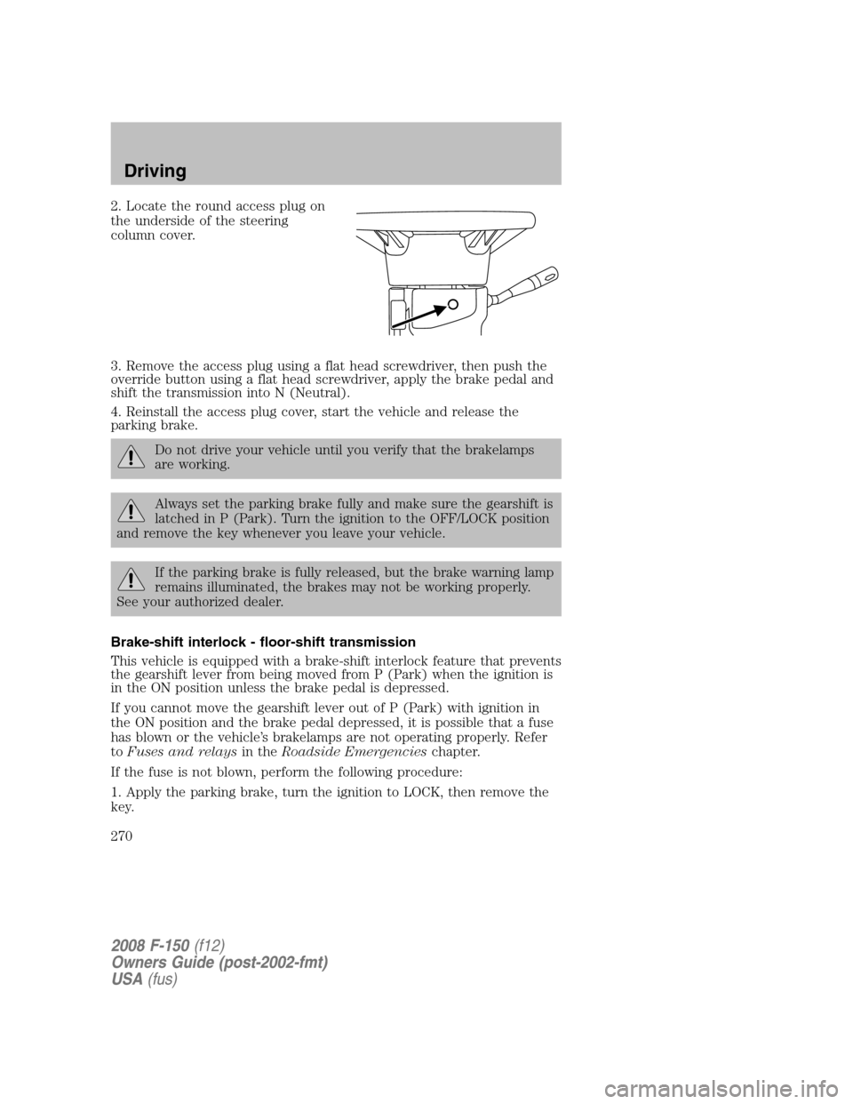
2. Locate the round access plug on
the underside of the steering
column cover.
3. Remove the access plug using a flat head screwdriver, then push the
override button using a flat head screwdriver, apply the brake pedal and
shift the transmission into N (Neutral).
4. Reinstall the access plug cover, start the vehicle and release the
parking brake.
Do not drive your vehicle until you verify that the brakelamps
are working.
Always set the parking brake fully and make sure the gearshift is
latched in P (Park). Turn the ignition to the OFF/LOCK position
and remove the key whenever you leave your vehicle.
If the parking brake is fully released, but the brake warning lamp
remains illuminated, the brakes may not be working properly.
See your authorized dealer.
Brake-shift interlock - floor-shift transmission
This vehicle is equipped with a brake-shift interlock feature that prevents
the gearshift lever from being moved from P (Park) when the ignition is
in the ON position unless the brake pedal is depressed.
If you cannot move the gearshift lever out of P (Park) with ignition in
the ON position and the brake pedal depressed, it is possible that a fuse
has blown or the vehicle’s brakelamps are not operating properly. Refer
toFuses and relaysin theRoadside Emergencieschapter.
If the fuse is not blown, perform the following procedure:
1. Apply the parking brake, turn the ignition to LOCK, then remove the
key.
2008 F-150(f12)
Owners Guide (post-2002-fmt)
USA(fus)
Driving
270
Page 294 of 400
•Headlight aim may require re-adjustment.
•The tire air pressures recommended for general driving are found on
the vehicle’s Safety Certification Label. The maximum cold inflation
pressure for the tire and associated load rating is imprinted on the tire
sidewall. Tire air pressure may require re-adjustment within these
pressure limits to accommodate the additional weight of the snowplow
installation
Operating the vehicle with the snowplow attached
Ford recommends that the F–150 be limited to low speed, personal-use
snow removal. Do not use your vehicle for snow removal until it has
been driven at least 500 miles (800 km).
The attached snowplow blade restricts airflow to the radiator, and may
cause the engine to run at a higher temperature. Attention to engine
temperature is especially important when outside temperatures are
above freezing. Angle the blade to maximize airflow to the radiator and
monitor engine temperature to determine whether a left or right angle
provides the best performance.
Snowplowing with your airbag equipped vehicle
Your vehicle is equipped with a driver and passenger air bag
Supplemental Restraint System (SRS) The SRS is designed to activate in
certain frontal and offset frontal collisions when the vehicle sustains
sufficient longitudinal deceleration.
Careless or high speed driving while plowing snow which results in
sufficient vehicle decelerations can deploy the airbag. Such driving also
increases the risk of accidents.
All occupants of the vehicle, including the driver, should always
properly wear their safety belts, even when an air bag
supplemental restraint system (SRS) is provided.
Never remove or defeat the “tripping mechanisms” designed into the
snow removal equipment by its manufacturer. Doing so may cause
damage to the vehicle and the snow removal equipment as well as
possible air bag deployment.
Do not attempt to service, repair, or modify the air bag
supplemental restraint system (SRS) or its fuses. See your Ford
or Lincoln Mercury dealer.
2008 F-150(f12)
Owners Guide (post-2002-fmt)
USA(fus)
Driving
294
Page 299 of 400

This switch is located in the front
passenger’s footwell, behind the kick
panel access cover, to the left of the
fuse box. The access cover needs to
be removed to reset the fuel pump
shut-off switch.
To reset the switch:
1. Turn the ignition OFF.
2. Check the fuel system for leaks.
3. If no leaks are apparent, reset the
switch by pushing in on the reset
button.
4. Turn the ignition ON.
5. Wait a few seconds and return
the key to OFF.
6. Make another check for leaks.
FUSES AND RELAYS
Fuses
If electrical components in the
vehicle are not working, a fuse may
have blown. Blown fuses are
identified by a broken wire within
the fuse. Check the appropriate
fuses before replacing any electrical
components.
Note:Always replace a fuse with one that has the specified amperage
rating. Using a fuse with a higher amperage rating can cause severe wire
damage and could start a fire.
15
2008 F-150(f12)
Owners Guide (post-2002-fmt)
USA(fus)
Roadside Emergencies
299
Page 300 of 400
Standard fuse amperage rating and color
COLOR
Fuse
ratingMini
fusesStandard
fusesMaxi
fusesCartridge
maxi
fusesFuse link
cartridge
2A Grey Grey — — —
3A Violet Violet — — —
4A Pink Pink — — —
5A Tan Tan — — —
7.5A Brown Brown — — —
10A Red Red — — —
15A Blue Blue — — —
20A Yellow Yellow Yellow Blue Blue
25A Natural Natural — — —
30A Green Green Green Pink Pink
40A — — Orange Green Green
50A — — Red Red Red
60A — — Blue Yellow Yellow
70A — — Tan — Brown
80A — — Natural Black Black
Passenger compartment fuse panel / power distribution box
The fuse panel is located under the right-hand side of the instrument
panel. Remove the trim panel and fuse box cover to access the fuses.
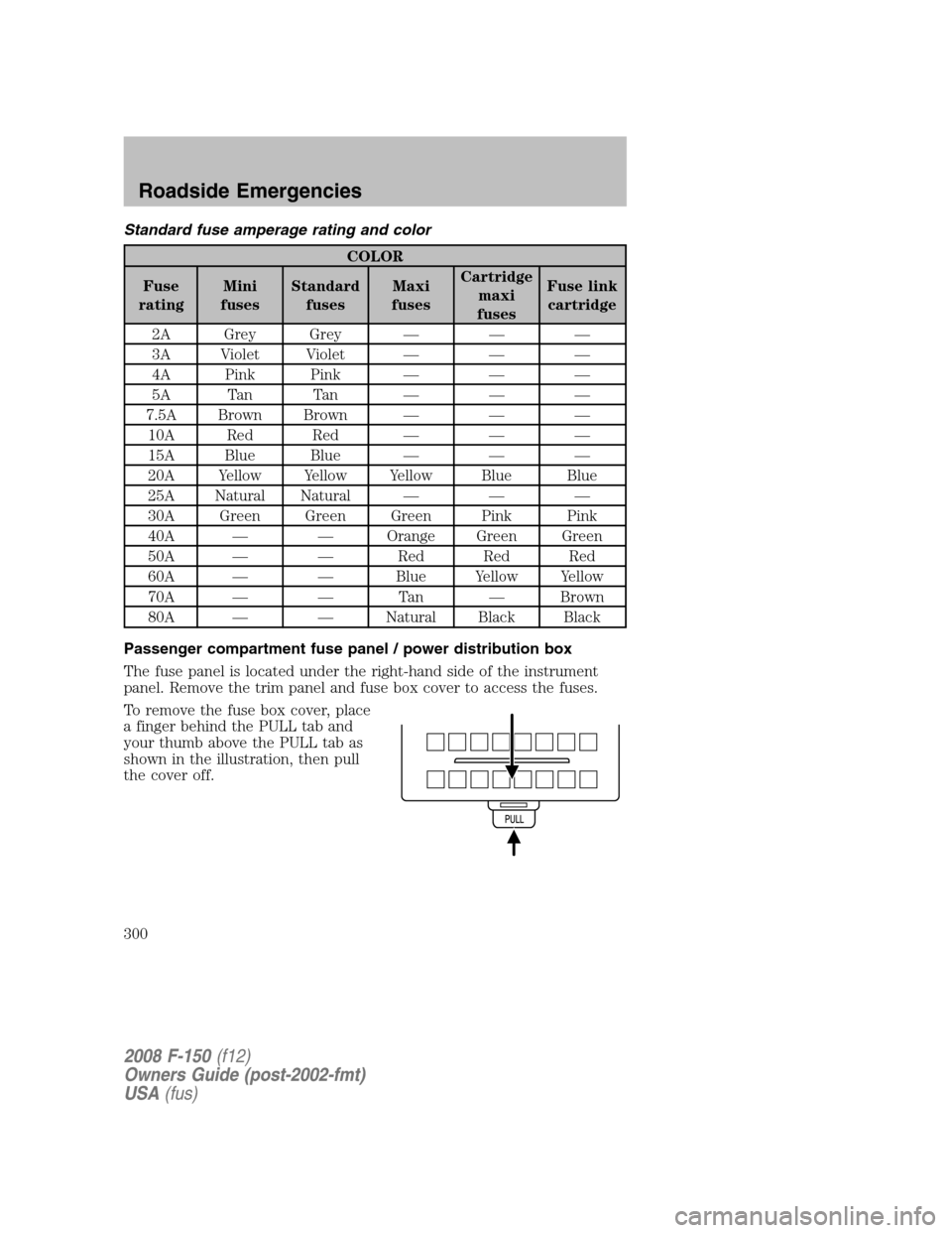
To remove the fuse box cover, place
a finger behind the PULL tab and
your thumb above the PULL tab as
shown in the illustration, then pull
the cover off.
2008 F-150(f12)
Owners Guide (post-2002-fmt)
USA(fus)
Roadside Emergencies
300