Page 100 of 400

3. Carefully pull the lamp assembly
straight rearward from the tailgate
pillar to disengage two hidden
snap-in retainers. (Flare side tail
lamps are not equipped with snap-in
retainers.)
4. Remove bulb socket from the
lamp assembly by turning it
counterclockwise.
5. Pull bulb straight out of socket
and press in the new bulb.
Install the new bulb(s) in reverse order.
Replacing high-mount brake and cargo lamp bulbs
Make sure the headlamp control is
in the OFF position.
1. Remove the two screws and move
the lamp assembly away from the
vehicle to expose the bulb sockets.
2. Remove the bulb socket by
rotating counterclockwise and
pulling it out of the lamp assembly.
3. Pull the bulb straight out of the socket and push in the new bulb.
Install the new bulbs in reverse order.
Replacing fog lamp bulbs (if equipped)
1. Make sure the headlamp control
is in the OFF position.
2. Remove the bulb socket from the
fog lamp by turning
counterclockwise.
3. Disconnect the electrical
connector from the fog lamp bulb.
Install the new bulb in reverse order.
Replacing exterior mounted mirror turn signal indicator lamp bulbs
For bulb replacement, see your authorized dealer.
2008 F-150(f12)
Owners Guide (post-2002-fmt)
USA(fus)
Lights
100
Page 101 of 400
Replacing license plate lamp bulbs
The license plate bulbs are located
behind the rear bumper. To change
the license plate lamp bulbs:
1. Reach behind the rear bumper to
locate the bulb.
2. Twist the bulb socket
counterclockwise and carefully pull
to remove it from the lamp
assembly.
3. Pull out the old bulb from the
socket and push in the new bulb.
4. Install the bulb socket in lamp assembly by turning it clockwise.
2008 F-150(f12)
Owners Guide (post-2002-fmt)
USA(fus)
Lights
101
Page 112 of 400

Automatic dimming interior rear view mirror (if equipped)
Your vehicle may be equipped with
an interior rear view mirror that has
an auto-dimming function (optional
on the driver’s side exterior mirror).
The electronic day/night mirror will
change from the normal (high
reflective) state to the non-glare
(darkened) state when bright lights
(glare) reach the interior mirror. When the interior mirror detects bright
light from behind the vehicle, the interior rear view mirror and the
driver’s side exterior mirror (if equipped) will automatically adjust
(darken) to minimize glare.
The mirrors will automatically return to the normal state whenever the
vehicle is placed in R (Reverse) to ensure a bright clear view when
backing up.
Do not block the sensors on the front and back of the interior
rear view mirror since this may impair proper mirror
performance.
Do not clean the housing or glass of any mirror with harsh
abrasives, fuel or other petroleum-based cleaning products.
Note:If equipped with a Reverse Camera System, a video image will
display in the mirror when the vehicle is put in (R) reverse. As you shift
into any other gear from (R) Reverse, the image will remain for a few
seconds and then turn off. Refer toReverse Camera Systemin the
Drivingchapter.
EXTERIOR MIRRORS
Power side view mirrors (if equipped)
To adjust your mirrors:
1. Rotate the control clockwise to
adjust the right mirror and rotate
the control counterclockwise to
adjust the left mirror.
2. Move the control in the direction
you wish to tilt the mirror.
3. Return to the center position to
lock mirrors in place.
2008 F-150(f12)
Owners Guide (post-2002-fmt)
USA(fus)
Driver Controls
112
Page 136 of 400

BED EXTENDER (IF EQUIPPED)
Your vehicle may be equipped with a bed extender designed to extend
the pickup box for larger loads.
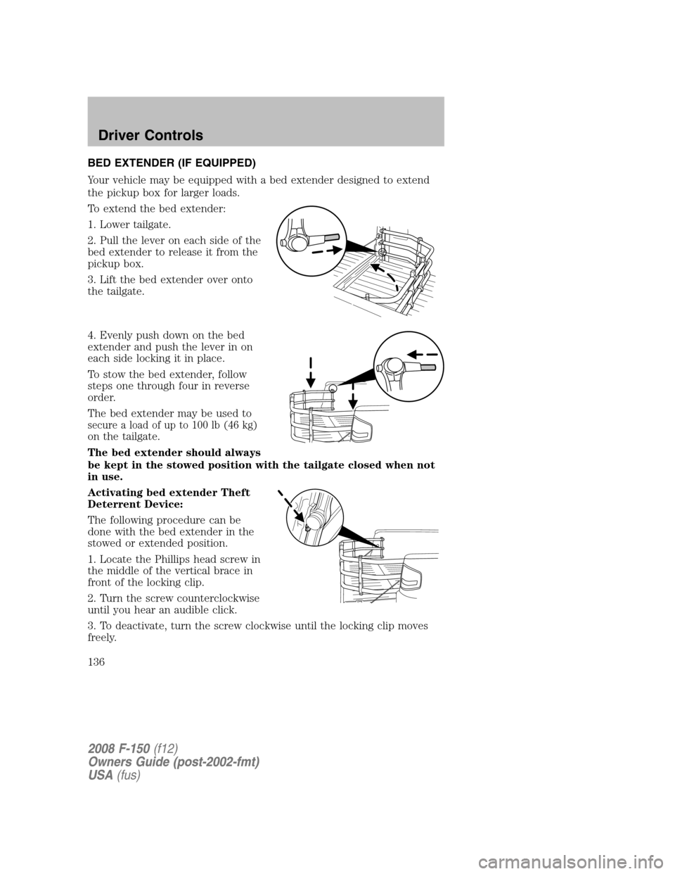
To extend the bed extender:
1. Lower tailgate.
2. Pull the lever on each side of the
bed extender to release it from the
pickup box.
3. Lift the bed extender over onto
the tailgate.
4. Evenly push down on the bed
extender and push the lever in on
each side locking it in place.
To stow the bed extender, follow
steps one through four in reverse
order.
The bed extender may be used to
secure a load of up to 100 lb (46 kg)
on the tailgate.
The bed extender should always
be kept in the stowed position with the tailgate closed when not
in use.
Activating bed extender Theft
Deterrent Device:
The following procedure can be
done with the bed extender in the
stowed or extended position.
1. Locate the Phillips head screw in
the middle of the vertical brace in
front of the locking clip.
2. Turn the screw counterclockwise
until you hear an audible click.
3. To deactivate, turn the screw clockwise until the locking clip moves
freely.
2008 F-150(f12)
Owners Guide (post-2002-fmt)
USA(fus)
Driver Controls
136
Page 233 of 400

If reset mode has been entered successfully, the horn will sound once,
the TPMS indicator will flash and the message center will displayTRAIN
LF TIRE.
If after repeated attempts to enter reset mode, the horn does not sound,
the TPMS indicator does not flash and the message center does not
display TRAIN LF TIRE, seek service from your authorized dealer.
TPMS reset sequence
The TPMS system needs to be reset starting with the left front tire in
the following clockwise order:
1. Left front tire
2. Right front tire
3. Right rear tire
4. Left rear tire
1.Left front tire:Place the TPMS reset tool against the left front tire
where the tire meets the rim, opposite from the valve stem (1) as shown.
This is where the sensor is located inside the rim.
The tool needs to be held against the tire sidewall opposite the
valve stem as illustrated with the arrow on the tool pointing
towards the rim; do not use the tool with the arrow pointing away
from the rim as it may not activate the sensor.
2. Press and release the green button and hold the tool to the tire
sidewall until the horn sounds. The red light on the TPMS reset tool will
2008 F-150(f12)
Owners Guide (post-2002-fmt)
USA(fus)
Tires, Wheels and Loading
233
Page 306 of 400
Auxiliary relay box
The relay box is located in the engine compartment on the left fender.
•With Daytime Running Lamp (DRL) or 4x4 options
•Without Daytime Running Lamp (DRL) and 4x4 options
The relays are coded as follows:
Fuse/Relay
LocationFuse Amp
RatingDescription
F03 5A Clockspring illumination
R01 Full ISO Relay 4x4 CCW
R02 Full ISO Relay 4x4 CW
R03
1⁄2ISO Relay Daytime Running Lamps (DRL) high
beam disable
R201 Relay DRL
R202 Relay A/C clutch
D01 Diode A/C clutch
D02 Diode One Touch Integrated Start (OTIS)
2008 F-150(f12)
Owners Guide (post-2002-fmt)
USA(fus)
Roadside Emergencies
306
Page 309 of 400

When driving with the full-size dissimilar spare tire/wheel additional
caution should be given to:
•Towing a trailer
•Driving vehicles equipped with a camper body
•Driving vehicles with a load on the cargo rack
Drive cautiously when using a full-size dissimilar spare tire/wheel and
seek service as soon as possible.
Location of the spare tire and tools
The spare tire and tools for your vehicle are stowed in the following
locations:
Tool Location
Spare tire Under the vehicle, just forward of
the rear bumper
Jack, jack handle and lug nut
wrenchRegular Cab: Behind the interior
trim on the passenger side of the
cab
SuperCrew and SuperCab: Under
the rear seat on the passenger side
The wing nut must be removed and the jack screw turned
counterclockwise to release pressure before the jack can be removed
from the holder.
Removing the spare tire
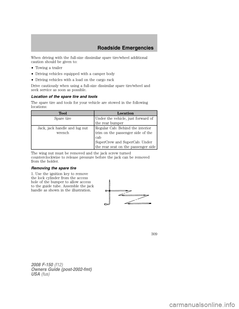
1. Use the ignition key to remove
the lock cylinder from the access
hole of the bumper to allow access
to the guide tube. Assemble the jack
handle as shown in the illustration.
2008 F-150(f12)
Owners Guide (post-2002-fmt)
USA(fus)
Roadside Emergencies
309
Page 310 of 400

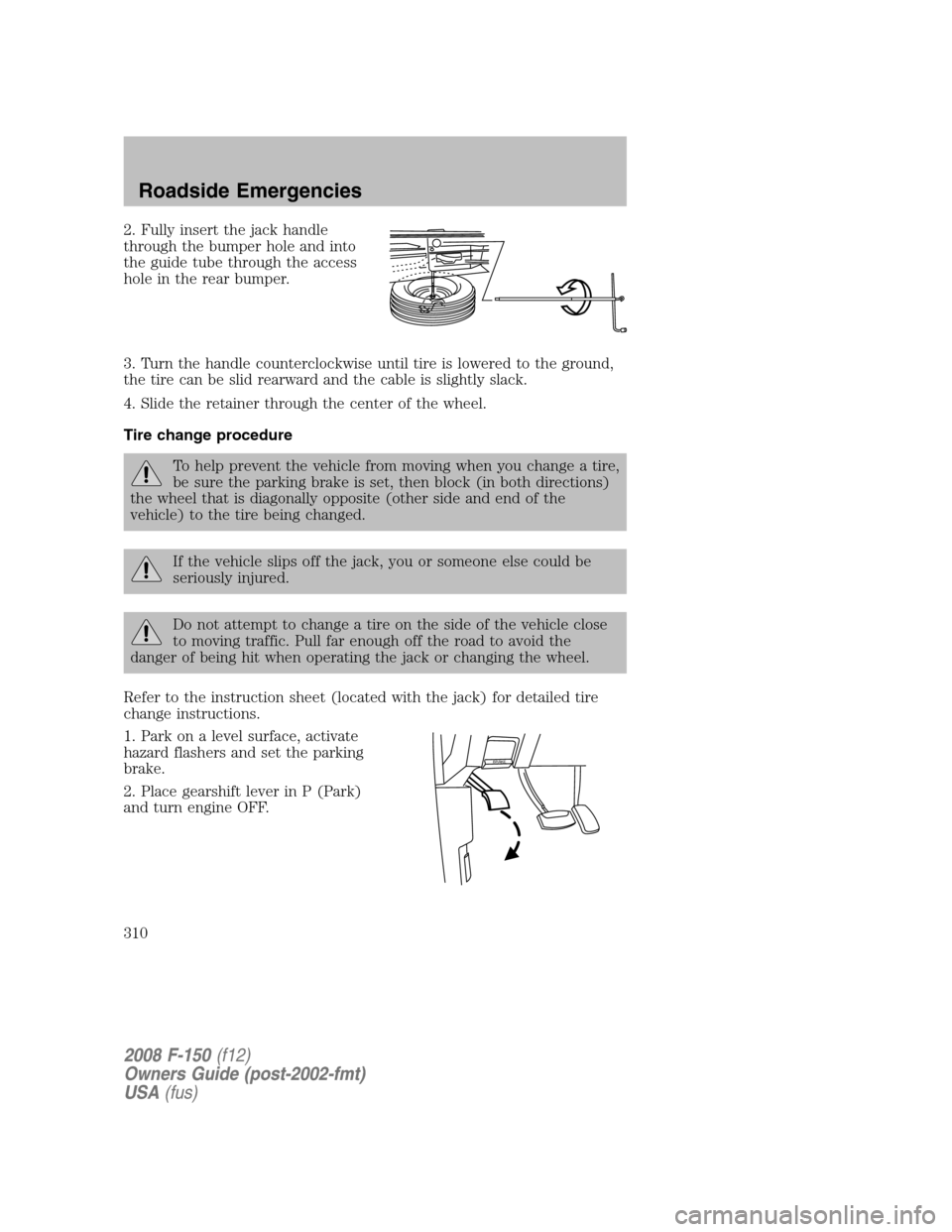
2. Fully insert the jack handle
through the bumper hole and into
the guide tube through the access
hole in the rear bumper.
3. Turn the handle counterclockwise until tire is lowered to the ground,
the tire can be slid rearward and the cable is slightly slack.
4. Slide the retainer through the center of the wheel.
Tire change procedure
To help prevent the vehicle from moving when you change a tire,
be sure the parking brake is set, then block (in both directions)
the wheel that is diagonally opposite (other side and end of the
vehicle) to the tire being changed.
If the vehicle slips off the jack, you or someone else could be
seriously injured.
Do not attempt to change a tire on the side of the vehicle close
to moving traffic. Pull far enough off the road to avoid the
danger of being hit when operating the jack or changing the wheel.
Refer to the instruction sheet (located with the jack) for detailed tire
change instructions.
1. Park on a level surface, activate
hazard flashers and set the parking
brake.
2. Place gearshift lever in P (Park)
and turn engine OFF.
BRAKE
2008 F-150(f12)
Owners Guide (post-2002-fmt)
USA(fus)
Roadside Emergencies
310