Page 156 of 392

CHILDPROOF DOOR LOCKS
When these locks are set, the rear
doors cannot be opened from the
inside. The rear doors can be
opened from the outside when the
doors are unlocked.
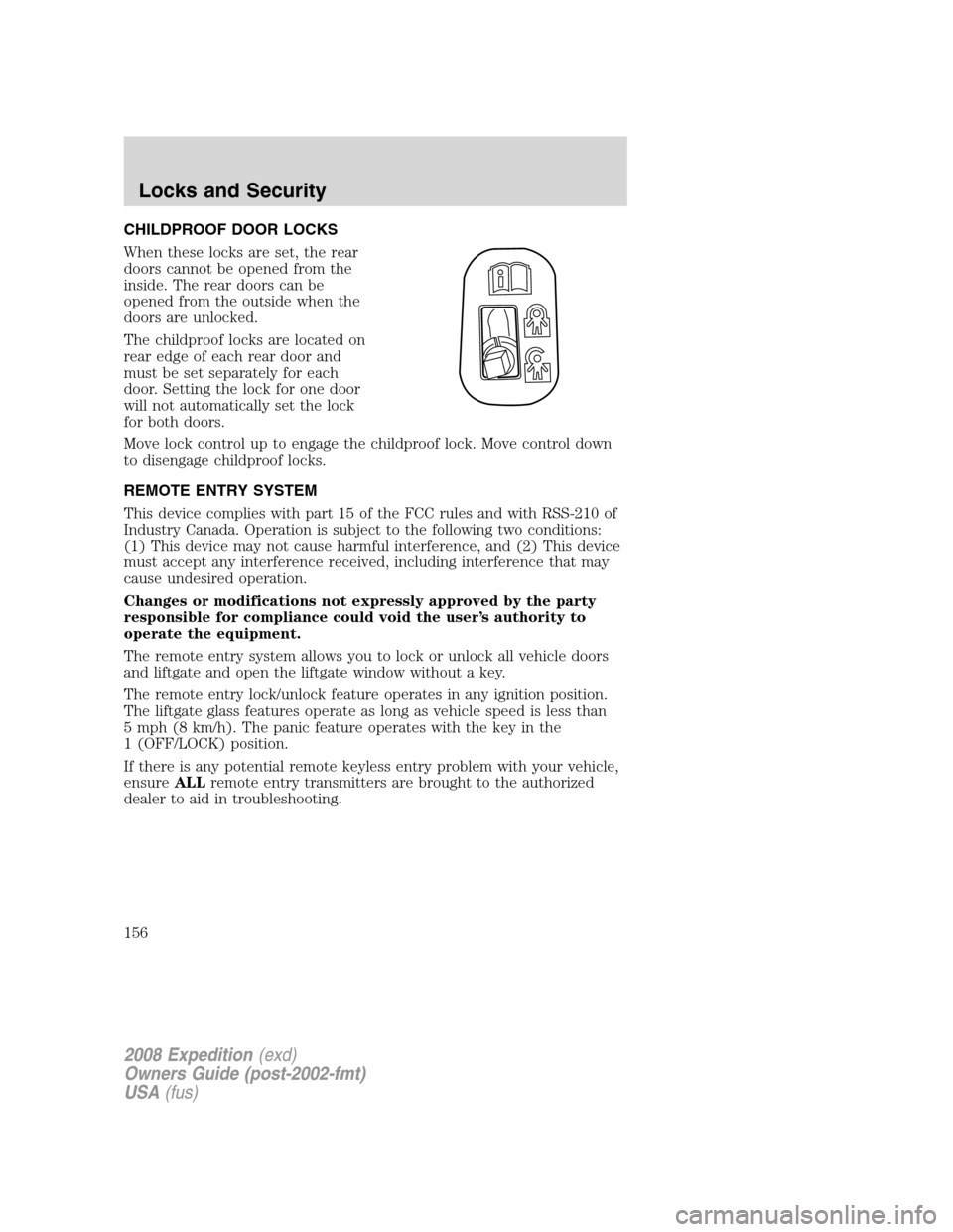
The childproof locks are located on
rear edge of each rear door and
must be set separately for each
door. Setting the lock for one door
will not automatically set the lock
for both doors.
Move lock control up to engage the childproof lock. Move control down
to disengage childproof locks.
REMOTE ENTRY SYSTEM
This device complies with part 15 of the FCC rules and with RSS-210 of
Industry Canada. Operation is subject to the following two conditions:
(1) This device may not cause harmful interference, and (2) This device
must accept any interference received, including interference that may
cause undesired operation.
Changes or modifications not expressly approved by the party
responsible for compliance could void the user’s authority to
operate the equipment.
The remote entry system allows you to lock or unlock all vehicle doors
and liftgate and open the liftgate window without a key.
The remote entry lock/unlock feature operates in any ignition position.
The liftgate glass features operate as long as vehicle speed is less than
5 mph (8 km/h). The panic feature operates with the key in the
1 (OFF/LOCK) position.
If there is any potential remote keyless entry problem with your vehicle,
ensureALLremote entry transmitters are brought to the authorized
dealer to aid in troubleshooting.
2008 Expedition(exd)
Owners Guide (post-2002-fmt)
USA(fus)
Locks and Security
156
Page 158 of 392
•4–button remote
•5–button remote
If any of the doors or liftgate are ajar, the horn will make two quick
chirps, reminding you to properly close all doors.
Opening the liftgate window
Press the control to unlatch the liftgate window.
•4–button remote
2008 Expedition(exd)
Owners Guide (post-2002-fmt)
USA(fus)
Locks and Security
158
Page 210 of 392

•Two crash sensors mounted in the front doors (one on each side of
the vehicle).
•Two crash sensors located at the C pillar behind the rear doors (one
on each side of the vehicle).
•Rollover sensor in the restraints control module (RCM).
The Safety Canopy™ system, in combination with safety belts, can help
reduce the risk of severe injuries in the event of a significant side impact
collision or rollover event.
Children 12 years old and under should always be properly restrained in
the second or third row seats. The Safety Canopy™ will not interfere
with children restrained using a properly installed child or booster seat
because it is designed to inflate downward from the headliner above the
doors along the side window opening.
The Safety Canopy™ system is designed to activate when the vehicle
sustains lateral deceleration sufficient to cause the side crash sensor to
close an electrical circuit that initiates Safety Canopy™ inflation or when
a certain likelihood of a rollover event is detected by the rollover sensor.
The Safety Canopy™ is mounted to roof side-rail sheet metal, behind the
headliner, along the entire side of the vehicle. In certain lateral collisions
or rollover events, the Safety Canopy™ system will be activated,
regardless of which seats are occupied. The Safety Canopy™ is designed
to inflate between the side window area and occupants to further
enhance protection provided in side impact collisions and rollover events.
The fact that the Safety Canopy™ did not activate in a collision does not
mean that something is wrong with the system. Rather, it means the
forces were not of the type sufficient to cause activation. The Safety
Canopy™ is designed to inflate in certain side impact collisions or
rollover events, not in rear impact, frontal or near-frontal collisions,
unless the collision causes sufficient lateral deceleration or rollover.
Several Safety Canopy™ system components get hot after
inflation. Do not touch them after inflation.
2008 Expedition(exd)
Owners Guide (post-2002-fmt)
USA(fus)
Seating and Safety Restraints
210
Page 268 of 392

3. After idling for a few seconds, apply the brake, shift into gear and
drive.
Note:If the engine does not start within five seconds on the first try,
turn the key to OFF, wait 10 seconds and try again. If the engine still
fails to start, press the accelerator to the floor and try again; this will
allow the engine to crank with the fuel shut off in case the engine is
flooded with fuel.
This vehicle has a computer assisted cranking system which assists in
starting the engine. If the ignition key is turned to 4 (START) and then
released when the engine begins cranking, the engine may continue
cranking for up to 10 seconds or until the vehicle starts
Guarding against exhaust fumes
Carbon monoxide is present in exhaust fumes. Take precautions to avoid
its dangerous effects.
If you smell exhaust fumes inside your vehicle, have your dealer
inspect your vehicle immediately. Do not drive if you smell
exhaust fumes.
Important ventilating information
If the engine is idling while the vehicle is stopped for a long period of
time, open the windows at least one inch (2.5 cm) or adjust the heating
or air conditioning to bring in fresh air.
ENGINE BLOCK HEATER (IF EQUIPPED)
If your vehicle is factory-equipped
with an engine block heater, a
rubber cap/plug assembly will be
visibly attached to the grille on the
front of the vehicle. This assembly is
shipped in-vehicle for authorized
dealer installation. If not
factory-equipped, the engine block
heater can be purchased through
authorized dealer accessories.
Replacement rubber caps are
available through an authorized dealer, 3L1Z-6E088-AA.
An engine block heater warms the engine coolant which aids in starting
and allows the heater/defroster system to respond quickly. If your vehicle
2008 Expedition(exd)
Owners Guide (post-2002-fmt)
USA(fus)
Driving
268
Page 305 of 392
The fuses are coded as follows.
Fuse/Relay
LocationFuse Amp
RatingPassenger Compartment Fuse
Panel Description
1 30A Smart window #1
2 15A Driver side memory module
3 15A FES, Audio rear seat controls,
SDARS
4 30A Smart window #2
5 10A Keypad illumination, 3rd row seat
enable, Brake Shift Interlock
(BSI), SPDJB
6 20A Turn signals
7 10A Low beam headlamps (left)
8 10A Low beam headlamps (right)
9 15A Interior lights
10 15A Backlighting, Puddle lamps
11 10A Not used (Spare)
12 7.5A Power mirror switch, Driver seat
memory switch
13 7.5A Not used (Spare)
14 10A Power liftgate module – keep-alive
power
15 10A Climate control
16 15A Not used (Spare)
17 20A All lock motor feeds, Liftgate
release, Liftglass release
18 20A Not used (Spare)
19 25A Rear wiper
20 15A Adjustable pedals, Datalink
21 15A Fog lamps, Cornering lamps
22 15A Park lamps relay
23 15A High beam headlamps
24 20A Horn relay
2008 Expedition(exd)
Owners Guide (post-2002-fmt)
USA(fus)
Roadside Emergencies
305
Page 306 of 392
Fuse/Relay
LocationFuse Amp
RatingPassenger Compartment Fuse
Panel Description
25 10A Demand lamps, Glovebox, Visor
26 10A Instrument panel cluster
27 20A Ignition switch
28 5A Radio
29 5A Instrument panel cluster
30 5A Not used (Spare)
31 10A Compass, Automatic dimming rear
view mirror
32 10A Restraints control module
33 10A Not used (Spare)
34 5A Not used (Spare)
35 10A Rear park assist, 4x4, rear video
camera
36 5A PATS transceiver
37 10A Climate control
38 20A Subwoofer/Amp (Audiophile
radio)
39 20A Radio
40 20A Not used (Spare)
41 15A Not used (Spare)
42 10A Trailer tow battery charge coil
43 10A Rear wiper logic
44 10A Not used (Spare)
45 5A Front wiper logic
46 7.5A Climate control, Auxiliary relay
control
47 30A Circuit
BreakerPower windows, Moon roof
48 — Delayed accessory relay
2008 Expedition(exd)
Owners Guide (post-2002-fmt)
USA(fus)
Roadside Emergencies
306
Page 307 of 392
Power distribution box
The power distribution box is located in the engine compartment. The
power distribution box contains high-current fuses that protect your
vehicle’s main electrical systems from overloads.
Always disconnect the battery before servicing high current
fuses.
To reduce risk of electrical shock, always replace the cover to
the Power Distribution Box before reconnecting the battery or
refilling fluid reservoirs.
If the battery has been disconnected and reconnected, refer to the
Batterysection of theMaintenance and Specificationschapter.
The high-current fuses are coded as follows:
Fuse/Relay
LocationFuse
Amp
RatingPower Distribution Box Description
1 — Blower relay
2 — Not used
3 — Rear window defroster relay
4 30A** Third row seats (driver side)
5 30A ** Trailer tow connector (electric brake)
6 60A** ABS (valves)
2008 Expedition(exd)
Owners Guide (post-2002-fmt)
USA(fus)
Roadside Emergencies
307
Page 308 of 392
Fuse/Relay
LocationFuse
Amp
RatingPower Distribution Box Description
7 — Not used
8 40A** Heated/cooled seats
9 60A** ABS (pump)
10 20A** Rear console power point
11 30A** Auxiliary blower
12 25A* Trailer tow connector (park lamps)
13 30A * Trailer tow connector (battery charge)
14 — Not used
15 — Not used
16 — A/C clutch relay
17 — Not used
18 — Fuel pump relay
19 — Back-up relay
20 — Trailer tow connector relay (left turn signal)
21 — Trailer tow connector relay (right turn signal)
22 — Not used
23 15A* Heated mirrors
24 40A** Blower motor
25 — Not used
26 — Not used
27 30A** Power liftgate
28 40A** Rear window defroster, Heated mirror
29 30A** Passenger seat
30 10A* A/C clutch
31 15A* Brake lamps
32 20A* Fuel pump
33 20A* Back-up lamps
34 25A* Trailer tow connector (stop/turn lamps)
35 20A* 4x4 module
2008 Expedition(exd)
Owners Guide (post-2002-fmt)
USA(fus)
Roadside Emergencies
308