2008 DODGE RAM 3500 GAS spare wheel
[x] Cancel search: spare wheelPage 430 of 554

²Connect the jack tube extension and wheel wrench.
Before raising the wheel off the ground, make sure
that the jack will not damage surrounding truck
parts and adjust the jack position as required.
NOTE:If the 2500/3500 bottle jack will not lower by
turning the dial (thumbwheel) by hand, it may be neces-
sary to use the jack drive tube in order to lower the jack.
4. By rotating the wheel wrench clockwise, raise the
vehicle until the wheel just clears the surface.
WARNING!
Raising the vehicle higher than necessary can make
the vehicle unstable and cause an accident. It could
slip off the jack and hurt someone near it. Raise the
vehicle only enough to remove the tire.5. Remove the wheel nuts and pull the wheel off. Install
the spare wheel and wheel nuts with the cone shaped end
of the nuts toward the wheel on 1500/2500/3500 single
rear-wheel (SRW) models. On 3500 dual rear-wheel mod-
els (DRW) the lug nuts are a two-piece assembly with a
flat face. Lightly tighten the nuts. To avoid risk of forcing
the vehicle off the jack, do not fully tighten the nuts until
the vehicle has been lowered.
6. Using the wheel wrench, finish tightening the nuts
using a crisscross pattern. Correct nut tightness is 135 ft
lbs (183 N´m) torque for 1500/2500/3500 single-rear
wheel (SRW) models, and 145 ft lbs (197 N´m) for 3500
dual rear-wheel models. If in doubt about the correct
tightness, have them checked with a torque wrench by
your authorized dealer or at a service station.
428 WHAT TO DO IN EMERGENCIES
Page 431 of 554

WARNING!
A loose tire or jack thrown forward in a collision or
hard stop could injure someone in the vehicle. Al-
ways stow the jack parts and the extra tire and wheel
in the places provided.
7. Install wheel center cap and remove wheel blocks. Do
not install chrome or aluminum wheel center caps on the
spare wheel. This may result in cap damage.
8. Lower the jack to its fully closed position. If the bottle
jack will not lower by turning the dial (thumbwheel) by
hand, it may be necessary to use the jack drive tube in
order to lower the jack. Stow the replaced tire, jack, and
tools as previously described.
9. Adjust the tire pressure when possible.NOTE:Do not oil wheel studs. For chrome wheels, do
not substitute with chrome plated wheel nuts.Hub Caps/Wheel Covers
The hub caps must be removed before raising the vehicle
off the ground.
For 2500/3500 single rear-wheel (SRW) models, use the
blade on the end of the lug wrench to pry the hub cap off.
Insert the blade end into the pryoff notch and carefully
pop off the hub cap with a back-and-forth motion.
On 3500 models with dual rear wheels (DRW), you must
first remove the hub caps. The jack handle driver has a
hook at one end that will fit in the pry off notch of the
rear hub caps. Position the hook and pull out on the
ratchet firmly. The hub cap should pop off. The wheel
skins can now be removed. For the front hub cap on 3500
models use the blade on the end of the lug wrench to pry
the caps off. The wheel skin can now be removed.
WHAT TO DO IN EMERGENCIES 429
6
Page 433 of 554

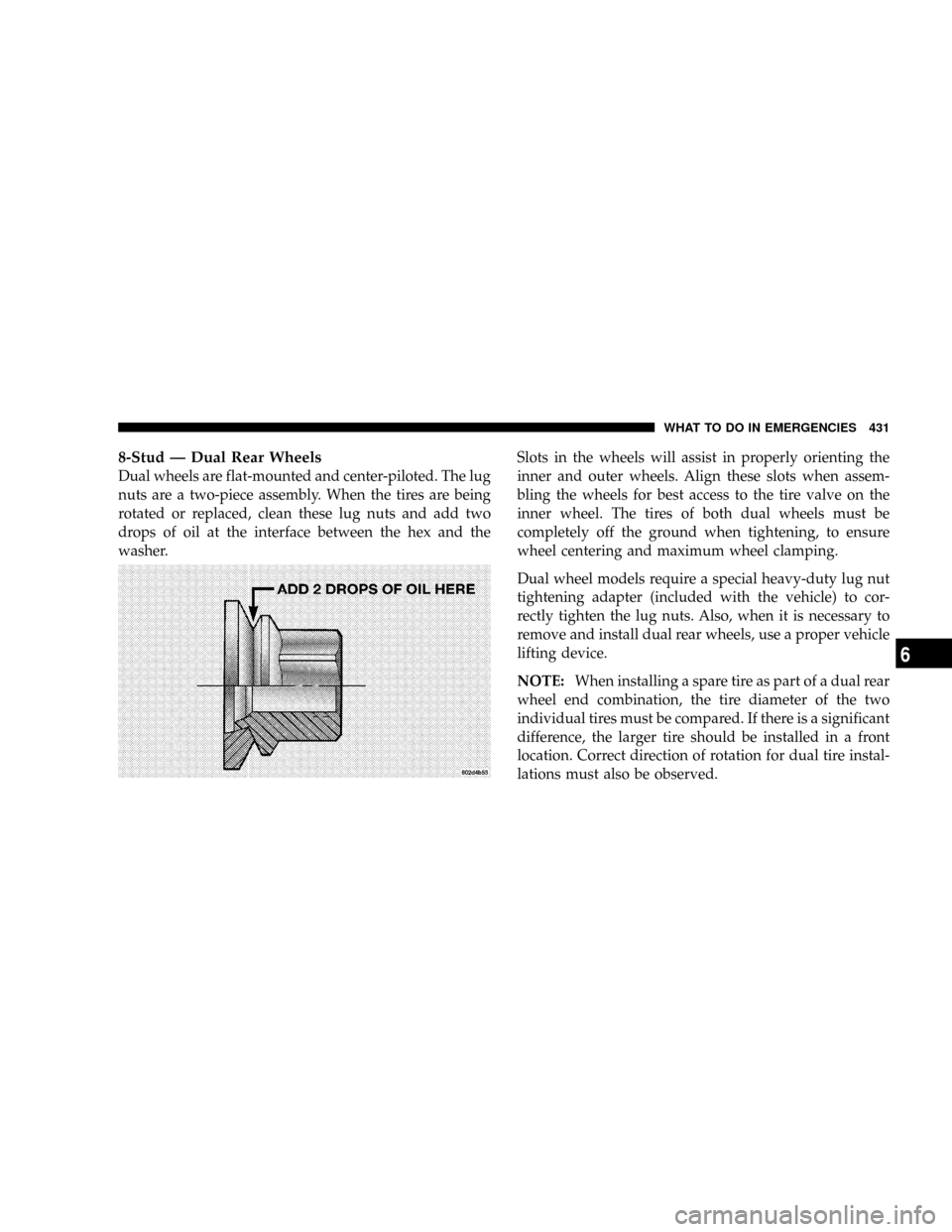
8-Stud Ð Dual Rear Wheels
Dual wheels are flat-mounted and center-piloted. The lug
nuts are a two-piece assembly. When the tires are being
rotated or replaced, clean these lug nuts and add two
drops of oil at the interface between the hex and the
washer.Slots in the wheels will assist in properly orienting the
inner and outer wheels. Align these slots when assem-
bling the wheels for best access to the tire valve on the
inner wheel. The tires of both dual wheels must be
completely off the ground when tightening, to ensure
wheel centering and maximum wheel clamping.
Dual wheel models require a special heavy-duty lug nut
tightening adapter (included with the vehicle) to cor-
rectly tighten the lug nuts. Also, when it is necessary to
remove and install dual rear wheels, use a proper vehicle
lifting device.
NOTE:When installing a spare tire as part of a dual rear
wheel end combination, the tire diameter of the two
individual tires must be compared. If there is a significant
difference, the larger tire should be installed in a front
location. Correct direction of rotation for dual tire instal-
lations must also be observed.
WHAT TO DO IN EMERGENCIES 431
6
Page 435 of 554

tightened to recommended torque. Tighten the nuts to
final torque in increments. Progress around the bolt
circle, tightening the nut opposite to the nut just previ-
ously tightened until final torque is achieved. Recom-
mended torques are shown in the following chart.
Disc
WheelsType Nut Stud Size Torque
Ft. Lbs.Torque
Newton
Meters
Cone 9/16-18 120-150 160-200
Flanged 9/16-18 130-160 190-220
To Stow The Flat Or Spare
NOTE: 1500 Regular and Quad Cabtvehicles
equipped with aluminum wheels cannot be stored under
the vehicle because the wheel retainer will not fit through
the wheel pilot hole. Secure the (flat) tire in the bed of the
truck.Have the (flat) tire repaired or replaced immedi-
ately.
WARNING!
A loose tire thrown forward in a collision or hard stop
could injure the occupants in the vehicle. Have the
deflated (flat) tire repaired or replaced immediately.
Turn the wheel so that the valve stem is down. Slide the
wheel retainer through the center of the wheel and
position it properly across the wheel opening.
For convenience in checking the spare tire inflation, stow
with the valve stem toward the rear of the vehicle.
Attach the wheel wrench to the extension tube. Rotate the
winch mechanism until the wheel is drawn into place
against the underside of the vehicle. Continue to rotate
until you feel the winch mechanism slip, or click three or
four times. It cannot be overtightened. Push against the
tire several times to be sure it is firmly in place.
WHAT TO DO IN EMERGENCIES 433
6
Page 536 of 554

Cassette Tape and Player Maintenance......... 257
Catalytic Converter...................... 455
CD (Compact Disc) Player............ 211,219,233
Cellular Phone.......................... 91
Center High Mounted Stop Light............ 502
Center Lap Belts......................... 45
Center Seat Storage Compartment.........173,174
Certification Label....................... 381
Chart, Tire Sizing........................ 340
Check Engine Light
(Malfunction Indicator Light)............... 201
Child Restraint........................62,63
Child Restraint Tether Anchors.............66,71
Child Seat............................63,70
Cigar Lighter........................... 168
Cleaning
Wheels............................. 486
Climate Control......................... 259
Clock.....................209,213,221,234,248Clutch............................... 474
Clutch Linkage Maintenance................ 474
Compact Disc (CD) Maintenance............. 258
Compact Spare Tire...................... 351
Compass...........................153,154
Compass Calibration..................... 154
Compass Variance....................... 155
Computer, Trip/Travel.................... 149
Console, Overhead....................... 148
Contract, Service........................ 525
Coolant Pressure Cap (Radiator Cap).......... 468
Cooling System......................... 465
Adding Coolant (Antifreeze).............. 467
Coolant Capacity...................... 508
Coolant Level......................465,469
Disposal of Used Coolant................ 469
Drain, Flush, and Refill.................. 466
Inspection........................... 469
Points to Remember.................... 469
534 INDEX
Page 548 of 554

Transfer Case......................... 297
Transfer Case, Shifting into Transfer Case
Neutral (N).........................407,409
Transfer Case, Shifting out of Transfer Case
Neutral (N).........................408,411
Shoulder Belt Upper Anchorage.............. 43
Shoulder Belts........................... 35
Signals, Turn........................... 139
Sliding Rear Window
Power.............................. 182
Slippery Surfaces, Driving On............... 314
Snow Chains (Tire Chains)................. 357
Snow Plow............................ 401
Snow Tires............................ 359
Spare Tire..........................351,352
Spark Plugs.........................454,510
Speed Control (Cruise Control).............. 145
Speedometer........................... 197
Starting.............................25,278Automatic Transmission................. 279
Engine Fails to Start.................... 280
Manual Transmission................... 279
Remote.............................. 25
Starting Procedures (Gas Engines)............ 278
Steering
Linkage............................. 461
Power...........................323,460
Wheel Lock........................... 18
Wheel, Tilt........................... 143
Steering Wheel Mounted Sound System
Controls.............................. 255
Storage, Behind the Seat................... 173
Storage Compartment, Center Seat.........173,174
Storage, Vehicle......................... 493
Storing Your Vehicle...................... 493
Sun Roof.............................. 163
Supplemental Tire Pressure Information........ 357
Sway Control, Trailer..................... 337
546 INDEX