Page 344 of 527
ªLight Loadº Reset Switch Operation ± If
Equipped
²
This vehicle may have different recommended tire
pressure values between the front and rear tires as
shown in both the Tire Loading Information Label and
the Supplemental Tire Pressure Information Label. It is
also equipped to be driven with tire pressures appro-
priate to either a Light Load condition or the vehicle
Max Load condition.
²The ªLight Loadº reset switch will allow the driver to
change between the max load inflation pressure (cold)
low pressure warning threshold and the light load
inflation pressure (cold) low pressure warning thresh-
old depending on the vehicle's load condition. Refer to
the ªSupplemental Tire Pressure Informationº label for
the vehicle's Light Load inflation pressures and ªTire
and Loading Informationº label for the vehicle's Max
Load inflation pressures.
Light Load Reset Switch
342 STARTING AND OPERATING
Page 345 of 527
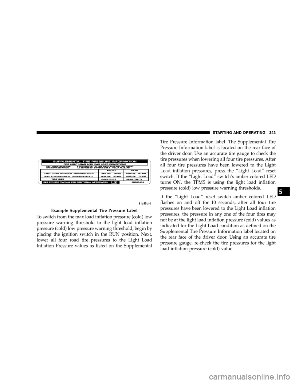
To switch from the max load inflation pressure (cold) low
pressure warning threshold to the light load inflation
pressure (cold) low pressure warning threshold, begin by
placing the ignition switch in the RUN position. Next,
lower all four road tire pressures to the Light Load
Inflation Pressure values as listed on the SupplementalTire Pressure Information label. The Supplemental Tire
Pressure Information label is located on the rear face of
the driver door. Use an accurate tire gauge to check the
tire pressures when lowering all four tire pressures. After
all four tire pressures have been lowered to the Light
Load inflation pressures, press the ªLight Loadº reset
switch. If the ªLight Loadº switch's amber colored LED
turns ON, the TPMS is using the light load inflation
pressure (cold) low pressure warning thresholds.
If the ªLight Loadº reset switch amber colored LED
flashes on and off for 10 seconds, after all four tire
pressures have been lowered to the Light Load inflation
pressures, the pressure in any one of the four tires may
not be at the light load inflation pressure (cold) values as
indicated for the Light Load condition as defined on the
Supplemental Tire Pressure Information label located on
the rear face of the driver door. Using an accurate tire
pressure gauge, re-check the tire pressures for the light
load inflation pressure (cold) value.
Example Supplemental Tire Pressure Label
STARTING AND OPERATING 343
5
Page 346 of 527
WARNING!
It is the driver 's responsibility to change to the max
load inflation pressure (cold) low pressure warning
threshold condition when not driving in the light
load condition as defined as two occupants ( 150 lbs
each) plus 200 pounds of cargo. The vehicle ªLight
Load Definitionº is found in the Supplemental Tire
Pressure Information label located on the rear face of
the driver door. Failure to do so may cause you to lose
control resulting in an accident, causing serious or
fatal injury.
To switch back to the max load inflation pressure (cold)
low pressure warning threshold, press the ªLight Loadº
reset switch. It is not necessary to first fill the tires to the
max load inflation pressure (cold) values to switch the
TPMS system to the max load inflation pressure (cold)low pressure warning threshold. If after pressing the
ªLight Loadº reset switch and tire pressures are below
the max load inflation pressure (cold) low pressure
warning thresholds, the TPMS low pressure warning
telltale lamp located in the Instrument Cluster will turn
ON and a chime will sound. The tire pressures are now
required to be inflated to the max load inflation pressure
(cold) values described on the Tire and Loading Informa-
tion label. The Tire and Loading Information label is
located on the drivers side B-pillar. If the ªLight Loadº
reset switch LED turns OFF the TPMS has been reset and
the TPMS is using the max load inflation pressure (cold)
low pressure warning thresholds.
Tire Pressure Monitor System Components
The Tire Pressure Monitor System (TPMS) uses wireless
technology with wheel rim mounted electronic sensors to
monitor tire pressure levels. Sensors, mounted to each
wheel as part of the valve stem, transmit tire pressure
readings to the Receiver Module.
344 STARTING AND OPERATING
Page 347 of 527
NOTE:It is particularly important, for you to check the
tire pressure in all of your tires regularly and to maintain
the proper pressure.
The Tire Pressure Monitoring System (TPMS) consists of
the following components:
²Receiver Module
²4 Wheel Sensors
²2 Trigger Modules (mounted in the front wheel-wells)
²ªLight Loadº Reset Switch (located in the instrument
panel)
²Tire Pressure Monitoring Telltale Lamp
Tire Pressure Monitoring Low Pressure Warnings
The Tire Pressure Monitoring Telltale Lamp will
illuminate in the instrument cluster, and an au-
dible chime will be activated when one or more of
the four active road tire pressures are low. Should this
occur, you should stop as soon as possible, check the
inflation pressure of each tire on your vehicle and inflate
each tire to the vehicle's recommended cold placard
pressure value. The system will automatically update
and the Tire Pressure Monitoring Lamp will extinguish
once the updated tire pressures have been received. The
vehicle may need to be driven for up to 10 minutes above
15 mph (25 km/h) to receive this information.
Check TPMS Warnings
The Tire Pressure Monitoring Telltale Warning Light
located in the Instrument Cluster will flash on and off for
75 seconds and will remain on solid when a system fault
is detected. The system fault will also sound a chime. If
STARTING AND OPERATING 345
5
Page 348 of 527
the ignition key is cycled, this sequence will repeat,
providing the system fault still exists. A system fault can
occur by any of the following scenarios:
1. Signal interference due to electronic devices or driving
next to facilities emitting the same Radio Frequencies as
the TPM sensors.
2. Installing aftermarket window tinting that affects ra-
dio wave signals.
3. Accumulation of snow or ice around the wheels or
wheel housings.
4. Using tire chains on the vehicle.
5. Using wheels/tires not equipped with TPM sensors.
6. Loss of communication with the trigger modules or
tire pressure monitoring sensors.
NOTE: Your vehicle is equipped with a non-matching
full size spare wheel and tire assembly.1. This spare tire does not have a tire pressure monitor-
ing sensor. Therefore, the TPMS will not monitor the tire
pressure in the spare tire.
2. If you install the full size spare tire in place of a road
tire that has a pressure below the low-pressure warning
limit, upon the next ignition key cycle, a chime will
sound and the TPM Telltale Light will still turn ON due
to the low tire.
3. However, after driving the vehicle for up to 10 min-
utes above 15 mph (25 km/h), the TPM Telltale Light will
flash on and off for 75 seconds and then remain on solid.
4. For each subsequent ignition key cycle, a chime will
sound and the TPM Telltale Light will flash on and off for
75 seconds and then remain on solid.
5. Once you repair or replace the original road tire, and
reinstall it on the vehicle in place of the full size spare tire,
the TPMS will update automatically and the TPM Telltale
346 STARTING AND OPERATING
Page 349 of 527
Light will turn OFF, as long as no tire pressure is below
the low-pressure warning limit in any of the four active
road tires. The vehicle may need to be driven for up to 10
minutes above 15 mph (25 km/h) in order for the TPMS
to receive this information.
General Information
This device complies with part 15 of the FCC rules and
RSS 210 of Industry Canada. Operation is subject to the
following conditions:
²This device may not cause harmful interference.
²This device must accept any interference received,
including interference that may cause undesired op-
eration.
The tire pressure sensors are covered under one of the
following licenses:
United States.....................KR5S120123
Canada........................2671-S120123
ENGINE RUNAWAY
WARNING!
In case of engine runaway due to flammable fumes
from gasoline spills or turbocharger oil leaks being
sucked into the engine, do the following to help
avoid personal injury and/or vehicle damage:
1. Shut off engine ignition switch.
2. Using a CO
2or dry chemical type fire extin-
guisher, direct the spray from the fire extinguisher
into the grille on the passenger side so that the spray
enters the engine air intake.
The inlet for the engine air intake is located behind
the passenger side headlamp and receives air
through the grille.
STARTING AND OPERATING 347
5
Page 367 of 527
þAn electronically actuated trailer brake controller is
required when towing a trailer with electronically
actuated brakes. When towing a trailer equipped with
a hydraulic surge actuated brake system, an electronic
brake controller is not required.
þTrailer brakes are recommended for trailers over 1,000
lbs (454 kg) and required for trailers in excess of 2,000
lbs (907 kg).
CAUTION!
If the trailer weighs more than 1,000 lbs (454 kg)
loaded, it should have its own brakes and they
should be of adequate capacity. Failure to do this
could lead to accelerated brake lining wear, higher
brake pedal effort, and longer stopping distances.
WARNING!
Do not connect trailer brakes to your vehicle's hy-
draulic brake lines. It can overload your brake sys-
tem and cause it to fail. You might not have brakes
when you need them and could have an accident.
Towing any trailer will increase your stopping dis-
tance. When towing you should allow for additional
space between your vehicle and the vehicle in front
of you. Failure to do so could result in an accident.
Towing Requirements Ð Trailer Lights & Wiring
Whenever you pull a trailer, regardless of the trailer size,
stop lights and turn signals on the trailer are required for
motoring safety.
STARTING AND OPERATING 365
5
Page 386 of 527
HAZARD WARNING FLASHER
The Hazard Warning switch is mounted on the top of the
steering column as shown in the illustration.To engage the Hazard Warning lights, depress the button
on the top of the steering column. When the Hazard
Warning switch is activated, all directional turn signals
will flash off and on to warn oncoming traffic of an
emergency. Push the button a second time to turn off the
flashers.
This is an emergency warning system and should not be
used when the vehicle is in motion. Use it when your
vehicle is disabled and is creating a safety hazard for
other motorists.
When you must leave the vehicle to seek assistance, the
Hazard Warning lights will continue to operate even
though the ignition switch is OFF.
NOTE:With extended use, the Hazard Warning lights
may discharge your battery.
Hazard Light Warning Switch
384 WHAT TO DO IN EMERGENCIES