Page 342 of 527
CAUTION!
After inspecting or adjusting the tire pressure always
reinstall the valve stem cap. This will prevent mois-
ture and dirt from entering the valve stem, which
could damage the Tire Pressure Monitoring Sensor.
NOTE:
²The TPMS is not intended to replace normal tire care
and maintenance, nor to provide warning of a tire
failure or condition.
²The TPMS should not be used as a tire pressure gauge
while adjusting your tire pressure.
²Driving on a significantly under-inflated tire causes
the tire to overheat and can lead to tire failure.
Under-inflation also reduces fuel efficiency and tire
tread life, and may affect the vehicle's handling and
stopping ability.
²The TPMS is not a substitute for proper tire mainte-
nance, and it is the driver 's responsibility to maintain
correct tire pressure, even if under-inflation has not
reached the level to trigger illumination of the ªTire
Pressure Monitoring Telltale Light.º
²Seasonal temperature changes will affect tire pressure,
and the TPM system will monitor the actual tire
pressure in the tire.
340 STARTING AND OPERATING
Page 343 of 527
Tire Pressure Monitor System (TPMS) ªLight
Loadº Reset Switch Description ± If Equipped
WARNING!
Never operate your vehicle with the TPMS and tire
pressures set to the Light Load Inflation Pressure
settings if carrying more than two occupants (150 lbs
each) plus 200 pounds of cargo. The vehicle ªLight
Load Definitionº is found in the Supplemental Tire
Pressure Information Label which is located on the
rear face of the driver door. Failure to do so may
cause you to lose control resulting in an accident,
causing serious or fatal injury.The TPMS ªLight Loadº reset switch will allow the driver
to switch between the max load inflation pressure (cold)
low pressure warning threshold and the light load infla-
tion pressure (cold) low pressure warning threshold
depending on the vehicle's load condition. The Tire and
Loading Information label defines the recommended
front and rear cold tire inflation pressures for the vehicle
when operating in the Max Load condition. A Supple-
mental Tire Pressure Information label is also available
defining Light Load tire inflation pressures when oper-
ating in the Light Load condition. When the ªLight Loadº
reset switch LED is ON, the TPMS is using the light load
inflation pressure (cold) low inflation warning thresh-
olds.
STARTING AND OPERATING 341
5
Page 344 of 527
ªLight Loadº Reset Switch Operation ± If
Equipped
²
This vehicle may have different recommended tire
pressure values between the front and rear tires as
shown in both the Tire Loading Information Label and
the Supplemental Tire Pressure Information Label. It is
also equipped to be driven with tire pressures appro-
priate to either a Light Load condition or the vehicle
Max Load condition.
²The ªLight Loadº reset switch will allow the driver to
change between the max load inflation pressure (cold)
low pressure warning threshold and the light load
inflation pressure (cold) low pressure warning thresh-
old depending on the vehicle's load condition. Refer to
the ªSupplemental Tire Pressure Informationº label for
the vehicle's Light Load inflation pressures and ªTire
and Loading Informationº label for the vehicle's Max
Load inflation pressures.
Light Load Reset Switch
342 STARTING AND OPERATING
Page 345 of 527
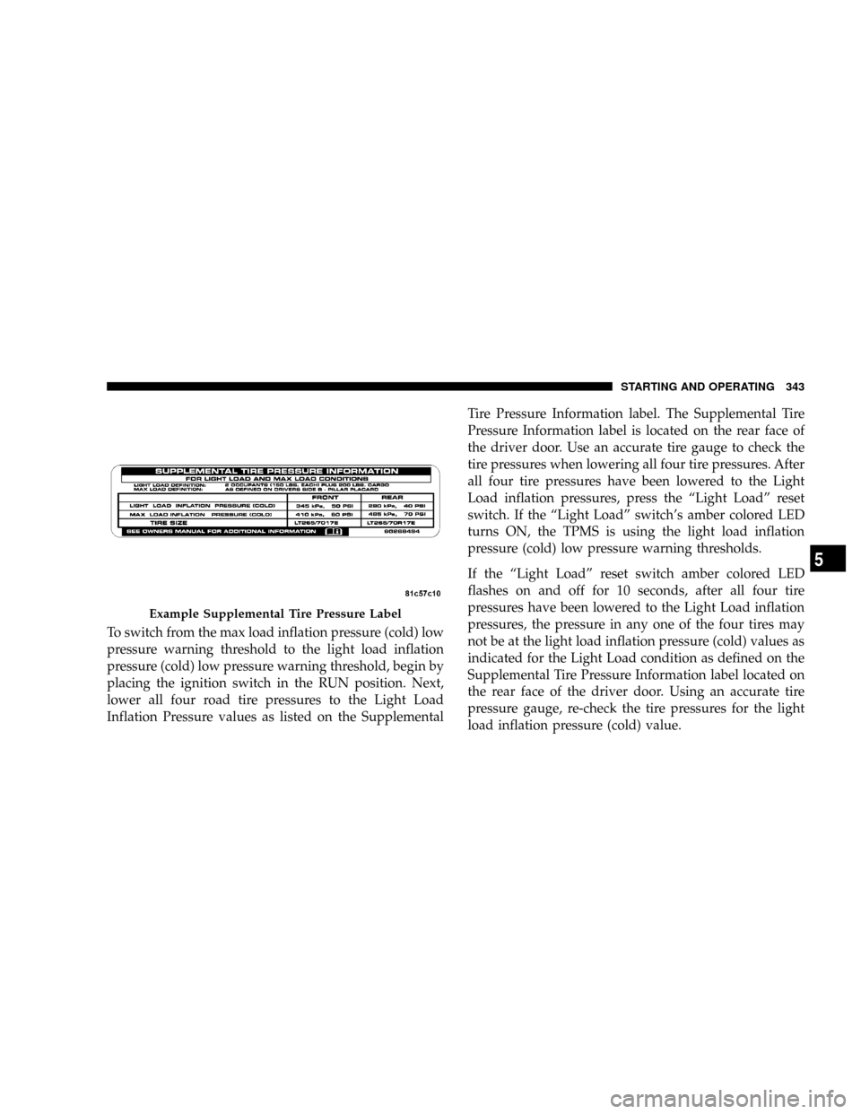
To switch from the max load inflation pressure (cold) low
pressure warning threshold to the light load inflation
pressure (cold) low pressure warning threshold, begin by
placing the ignition switch in the RUN position. Next,
lower all four road tire pressures to the Light Load
Inflation Pressure values as listed on the SupplementalTire Pressure Information label. The Supplemental Tire
Pressure Information label is located on the rear face of
the driver door. Use an accurate tire gauge to check the
tire pressures when lowering all four tire pressures. After
all four tire pressures have been lowered to the Light
Load inflation pressures, press the ªLight Loadº reset
switch. If the ªLight Loadº switch's amber colored LED
turns ON, the TPMS is using the light load inflation
pressure (cold) low pressure warning thresholds.
If the ªLight Loadº reset switch amber colored LED
flashes on and off for 10 seconds, after all four tire
pressures have been lowered to the Light Load inflation
pressures, the pressure in any one of the four tires may
not be at the light load inflation pressure (cold) values as
indicated for the Light Load condition as defined on the
Supplemental Tire Pressure Information label located on
the rear face of the driver door. Using an accurate tire
pressure gauge, re-check the tire pressures for the light
load inflation pressure (cold) value.
Example Supplemental Tire Pressure Label
STARTING AND OPERATING 343
5
Page 346 of 527
WARNING!
It is the driver 's responsibility to change to the max
load inflation pressure (cold) low pressure warning
threshold condition when not driving in the light
load condition as defined as two occupants ( 150 lbs
each) plus 200 pounds of cargo. The vehicle ªLight
Load Definitionº is found in the Supplemental Tire
Pressure Information label located on the rear face of
the driver door. Failure to do so may cause you to lose
control resulting in an accident, causing serious or
fatal injury.
To switch back to the max load inflation pressure (cold)
low pressure warning threshold, press the ªLight Loadº
reset switch. It is not necessary to first fill the tires to the
max load inflation pressure (cold) values to switch the
TPMS system to the max load inflation pressure (cold)low pressure warning threshold. If after pressing the
ªLight Loadº reset switch and tire pressures are below
the max load inflation pressure (cold) low pressure
warning thresholds, the TPMS low pressure warning
telltale lamp located in the Instrument Cluster will turn
ON and a chime will sound. The tire pressures are now
required to be inflated to the max load inflation pressure
(cold) values described on the Tire and Loading Informa-
tion label. The Tire and Loading Information label is
located on the drivers side B-pillar. If the ªLight Loadº
reset switch LED turns OFF the TPMS has been reset and
the TPMS is using the max load inflation pressure (cold)
low pressure warning thresholds.
Tire Pressure Monitor System Components
The Tire Pressure Monitor System (TPMS) uses wireless
technology with wheel rim mounted electronic sensors to
monitor tire pressure levels. Sensors, mounted to each
wheel as part of the valve stem, transmit tire pressure
readings to the Receiver Module.
344 STARTING AND OPERATING
Page 347 of 527
NOTE:It is particularly important, for you to check the
tire pressure in all of your tires regularly and to maintain
the proper pressure.
The Tire Pressure Monitoring System (TPMS) consists of
the following components:
²Receiver Module
²4 Wheel Sensors
²2 Trigger Modules (mounted in the front wheel-wells)
²ªLight Loadº Reset Switch (located in the instrument
panel)
²Tire Pressure Monitoring Telltale Lamp
Tire Pressure Monitoring Low Pressure Warnings
The Tire Pressure Monitoring Telltale Lamp will
illuminate in the instrument cluster, and an au-
dible chime will be activated when one or more of
the four active road tire pressures are low. Should this
occur, you should stop as soon as possible, check the
inflation pressure of each tire on your vehicle and inflate
each tire to the vehicle's recommended cold placard
pressure value. The system will automatically update
and the Tire Pressure Monitoring Lamp will extinguish
once the updated tire pressures have been received. The
vehicle may need to be driven for up to 10 minutes above
15 mph (25 km/h) to receive this information.
Check TPMS Warnings
The Tire Pressure Monitoring Telltale Warning Light
located in the Instrument Cluster will flash on and off for
75 seconds and will remain on solid when a system fault
is detected. The system fault will also sound a chime. If
STARTING AND OPERATING 345
5
Page 355 of 527
Gross Vehicle Weight Rating (GVWR)
The GVWR is the total permissible weight of your vehicle
including driver, passengers, vehicle, options and cargo.
The label also specifies maximum capacities of front and
rear axle systems (GAWR). Total load must be limited so
GVWR and front and rear GAWR are not exceeded.
Payload
The payload of a vehicle is defined as the allowable load
weight a truck can carry, including the weight of the
driver, all passengers, options and cargo.
Gross Axle Weight Rating (GAWR)
The GAWR is the maximum permissible load on the front
and rear axles. The load must be distributed in the cargo
area so that the GAWR of each axle is not exceeded.Each axle GAWR is determined by the components in the
system with the lowest load carrying capacity (axle,
springs, tires or wheels). Heavier axles or suspension
components sometimes specified by purchasers for in-
creased durability does not necessarily increase the vehi-
cle's GVWR.
Tire Size
The tire size on the Label represents the actual tire size on
your vehicle. Replacement tires must be equal to the load
capacity of this tire size.
Rim Size
This is the rim size that is appropriate for the tire size
listed.
Inflation Pressure
This is the cold tire inflation pressure for your vehicle for
all loading conditions up to full GAWR.
STARTING AND OPERATING 353
5
Page 366 of 527
2. GTW
3. GAWR
4. Tongue weight rating for the trailer hitch utilized
(This requirement may limit the ability to always
achieve the 10% to 15% range of tongue weight as a
percentage of total trailer weight).
Towing Requirements Ð Tires
þ
Do not attempt to tow a trailer while using a compact
spare tire.
þProper tire inflation pressures are essential to the safe
and satisfactory operation of your vehicle. Refer to the
Tires±General Information section of this manual on
Tire Pressures for proper tire inflation procedures.
þAlso, check the trailer tires for proper tire inflation
pressures before trailer usage.
þCheck for signs of tire wear or visible tire damage
before towing a trailer. Refer to the Tires±General
Information section of this manual on Tread Wear
Indicators for the proper inspection procedure.
þWhen replacing tires refer to the Tires±General Infor-
mation section of this manual on Replacement Tires for
proper tire replacement procedures. Replacing tires
with a higher load carrying capacity will not increase
the vehicle's GVWR and GAWR limits.
Towing Requirements Ð Trailer Brakes
þ
Donotinterconnect the hydraulic brake system or
vacuum system of your vehicle with that of the trailer.
This could cause inadequate braking and possible
personal injury.
364 STARTING AND OPERATING