2008 DODGE GRAND CARAVAN fuse
[x] Cancel search: fusePage 36 of 531
Lock Doors Automatically Ð If Equipped
If the Lock Doors Automatically feature is enabled, your
door locks will lock automatically when the vehicle's
speed exceeds 15 mph (24 km/h).
The Lock Doors Automatically feature is enabled when
your vehicle is shipped from the assembly plant and can
be disabled by using the following procedure:
²On Electronic Vehicle Information Center (EVIC)
equipped vehicles, refer to9Personal Settings9in the
EVIC section of this manual.
²On non EVIC-equipped vehicles perform the follow-
ing steps:
1. Enter your vehicle and close all doors.
2. Fasten your seat belt. (Fastening the seat belt will
cancel any chiming that may confuse you during this
programming procedure.)3. Place the key into the ignition.
4. Within 15 seconds cycle the ignition key from the OFF
position to the ON/RUN position a minimum of four
times, ending in the OFF position(do not start the
engine).
5. Within 30 seconds, press the driver's door lock switch
in the lock direction.
6. A single chime will be heard to indicate the feature has
been disabled.
7. To reactivate this feature, repeat the above steps.
8. If a chime is not heard, the program mode was
canceled before the feature could be disabled. If neces-
sary, repeat the above procedure.
34 THINGS TO KNOW BEFORE STARTING YOUR VEHICLE
Page 79 of 531
WARNING!
Do not attempt to modify any part of your advanced
airbag system. The airbag may inflate accidentally or
may not function properly if modifications are made.
Take your vehicle to an authorized dealer for any
advanced airbag system service. If your seat, includ-
ing your trim cover and cushion, needs to be serviced
in any way (including removal or loosening/
tightening of seat attachment bolts), take the vehicle
to your authorized dealer. Only manufacturer ap-
proved seat accessories may be used. If it is necessary
to modify an advanced airbag system for persons
with disabilities, contact your authorized dealer.
NOTE:
Perchlorate Material Ð special handling may ap-
ply. See: www.dtsc.ca.gov/hazardouswaste/perchlorate.
Airbag Light
You will want to have the airbags ready to
inflate for your protection in a collision. While
the airbag system is designed to be mainte-
nance free, if any of the following occurs, have
an authorized dealer service the system immediately.
²The AIRBAG light does not come on during the
approximately four to six seconds when the ignition
switch is first turned ON.
²The light remains on after the approximately four to
six-second interval.
²The light comes on and remains on while driving.
NOTE:If the speedometer, tachometer, or any engine
related gauges are not working, the Occupant Restraint
Controller (ORC) may also be disabled. The airbags may
not be ready to inflate for your protection. Promptly
check the fuse block for blown fuses. Refer to the label
THINGS TO KNOW BEFORE STARTING YOUR VEHICLE 77
2
Page 80 of 531
located on the inside of the fuse block cover for the
proper airbag fuses. See your authorized dealer if the
fuse is good.
Event Data Recorder (EDR)
In the event of an accident, your vehicle is designed to
record up to approximately five seconds of specific
vehicle data parameters (see the following list) in an
event data recorder prior to the moment of airbag de-
ployment, or near deployment, and up to a quarter-
second of high-speed deceleration data during and/or
after airbag deployment. EDR data are ONLY recorded if
an airbag deploys, or nearly deploys, and are otherwise
unavailable.
NOTE:
1. A near-deployment event occurs when the airbag
sensor detects severe vehicle deceleration usually indica-
tive of a crash, but not severe enough to warrant airbag
deployment.2. Under certain circumstances, EDR data may not be
recorded (e.g., loss of battery power).
In conjunction with other data gathered during a com-
plete accident investigation, the electronic data may be
used by DaimlerChrysler Corporation and others to learn
more about the possible causes of crashes and associated
injuries in order to assess and improve vehicle perfor-
mance. In addition to crash investigations initiated by
DaimlerChrysler Corporation, such investigations may
be requested by customers, insurance carriers, govern-
ment officials, and professional crash researchers, such as
those associated with universities, and with hospital and
insurance organizations.
In the event that an investigation is undertaken by
DaimlerChrysler Corporation (regardless of initiative),
the company or its designated representative will first
obtain permission of the appropriate custodial entity for
the vehicle (usually the vehicle owner or lessee) before
78 THINGS TO KNOW BEFORE STARTING YOUR VEHICLE
Page 232 of 531
replacement, be sure to keep a record of the reading
before and after the service so that the correct mileage can
be determined.
The trip odometer shows individual trip mileage. To
switch from odometer to trip odometer, press the Trip
Odometer button.
To reset a trip odometer, display the desired trip odom-
eter to be reset then push and hold the button until the
display resets (approximately two seconds).
12. PRNDL/Odometer Display Area
When the appropriate conditions exist, the following
odometer messages will display:
CHAngE OIL............... OilChange Required
CRUISE.....................Cruise Control On
door.............................Door Ajar
ESPOFF............................ ESPOffgATE..........................Lift Gate Ajar
gASCAP.......................Fuel Cap Fault
hood*............................Hood Ajar
noFUSE..........................Fuse Fault
LoCOOL........................ LowCoolant
LoWASH.................... LowWasher Fluid
NOTE:If your vehicle is equipped with an hood switch,
in the case of hood ajar, a warning message will be
displayed in either the PRNDL/Odometer display as
ªhoodº or ªHood Ajarº in the EVIC display.
NOTE:Some of the above warnings will be displayed in
the Compass Mini-Trip Computer / Electronic Vehicle
Information Center Display Area under the Speedometer.
CHAngE OIL
Your vehicle is equipped with an engine oil change
indicator system. The ªChange Oilº message will flash in
the instrument cluster odometer for approximately 12
230 UNDERSTANDING YOUR INSTRUMENT PANEL
Page 233 of 531

seconds after a single chime has sounded to indicate the
next scheduled oil change interval. The engine oil change
indicator system is duty cycle-based, which means the
engine oil change interval may fluctuate dependent upon
your personal driving style.
Unless reset, this message will continue to display each
time you turn the ignition switch to the ON/RUN
position. To turn off the message temporarily, press and
release the Trip Odometer button on the instrument
cluster. To reset the oil change indicator system (after
performing the scheduled maintenance) refer to the fol-
lowing procedure.
1. Turn the ignition switch to the ON position (Do not
start the engine).
2. Fully depress the accelerator pedal slowly three times
within 10 seconds.
3. Turn the ignition switch to the OFF/LOCK position.NOTE:If the indicator message illuminates when you
start the vehicle, the oil change indicator system did not
reset. If necessary repeat this procedure.
13. Odometer Display Reset Button
To reset a message display (gATE, gASCAP, noFUSE,
CHAngE OIL, LoCOOL, LoWASH), push and hold the
button until the display resets (approximately two sec-
onds).
14. Electronic Stability Program (ESP) Indicator
Light/Traction Control System (TCS) Indicator Light
If this indicator light flashes during accelera-
tion, apply as little throttle as possible. While
driving, ease up on the accelerator. Adapt your
speed and driving to the prevailing road con-
ditions, and do not switch off the ESP, or TCS.
UNDERSTANDING YOUR INSTRUMENT PANEL 231
4
Page 240 of 531
COMPASS MINI-TRIP COMPUTER (CMTC) Ð IF
EQUIPPED
NOTE:The compass on your vehicle is self-calibrating,
eliminating the need to manually calibrate the compass.
The Compass Mini-Trip Computer features a driver-
interactive display (displays information on outside tem-
perature, compass direction, and trip information). It is
located in the instrument cluster, below the Fuel and
Temperature gauges.
Compass Mini-Trip Computer (CMTC) Odometer
Displays
When the appropriate conditions exist, the following
odometer messages will display:
CHAngE OIL............... OilChange Required
CRUISE......................Cruise Activated
door.............................Door AjarESPOFF...................... ESPDeactivated
gATE..........................Lift Gate Ajar
gASCAP.......................Fuel Cap Fault
hood............................Hood Ajar
noFUSE..........................Fuse Fault
LoCOOL........................ LowCoolant
LoWASH.................... LowWasher Fluid
These messages can be manually turned off by pressing
the right reset button (on the instrument cluster).
Compass Mini-Trip Computer (CMTC) Reset
Buttons
CMTC Reset Button
Press the left reset button located on the instrument
cluster to scroll through the sub menus (i.e., Trip Func-
tions: AVG Fuel Economy, DTE, Elapsed Time, and
Units).
238 UNDERSTANDING YOUR INSTRUMENT PANEL
Page 434 of 531
NPower Steering Ð Fluid Check............452
NFront Suspension Ð Ball Joints............453
NSteering Shaft Seal....................453
NDrive Shaft Universal Joints..............454
NBody Lubrication.....................454
NWindshield Wiper Blades................454
NCooling System.......................456
NHoses And Vacuum/Vapor Harnesses.......461
NFuel System Connections................461
NBrakes.............................462
NAutomatic Transaxle...................464
NFront And Rear Wheel Bearings...........467NAppearance Care And Protection From
Corrosion...........................467
NCleaning The Instrument Panel Cup Holders . . 473
mFuses/Totally Integrated Power Module
(TIPM)..............................474
mVehicle Storage........................481
mReplacement Light Bulbs.................481
mBulb Replacement......................482
NHeadlights..........................482
NFront Park/Turn Signal And Side Marker
Lights.............................483
NFog Lights..........................483
NRear Tail, Stop, Turn Signal, Side Marker And
Backup Lights........................484
432 MAINTAINING YOUR VEHICLE
Page 476 of 531
Installation
Place the liner into the cupholder drawer and press the
liner into place so that the retention tabs seat into the
corresponding openings in the drawer.
FUSES/TOTALLY INTEGRATED POWER MODULE
(TIPM)
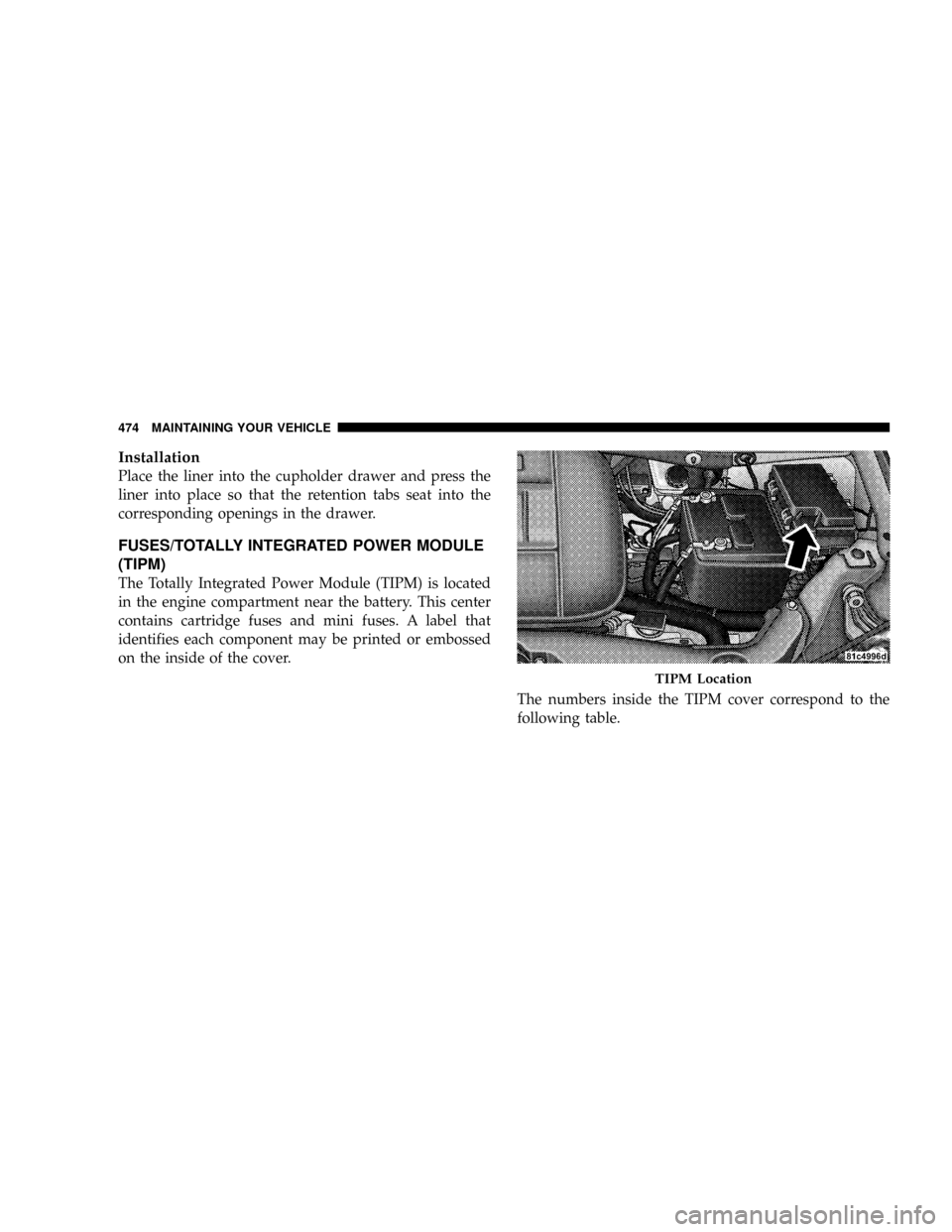
The Totally Integrated Power Module (TIPM) is located
in the engine compartment near the battery. This center
contains cartridge fuses and mini fuses. A label that
identifies each component may be printed or embossed
on the inside of the cover.
The numbers inside the TIPM cover correspond to the
following table.
TIPM Location
474 MAINTAINING YOUR VEHICLE