2008 DODGE CHARGER service
[x] Cancel search: servicePage 392 of 466

service attendant of this. As long as the engine operating
temperature is satisfactory, the coolant bottle need only
be checked once a month.
When additional coolant is needed to maintain the
proper level, it should be added to the coolant bottle. Do
not overfill.
Points To Remember
NOTE:When the vehicle is stopped after a few miles
(kilometers) of operation, you may observe vapor coming
from the front of the engine compartment. This is nor-
mally a result of moisture from rain, snow, or high
humidity accumulating on the radiator and being vapor-
ized when the thermostat opens, allowing hot coolant to
enter the radiator.
If an examination of your engine compartment shows no
evidence of radiator or hose leaks, the vehicle may be
safely driven. The vapor will soon dissipate.
²Do not overfill the coolant recovery bottle.
²Check coolant freeze point in the radiator and in the
coolant recovery bottle. If antifreeze needs to be
added, contents of coolant recovery bottle must also be
protected against freezing.
²If frequent coolant additions are required, or if the
level in the coolant recovery bottle does not drop when
the engine cools, the cooling system should be pres-
sure tested for leaks.
²Maintain coolant concentration at 50% HOAT engine
coolant (minimum) and distilled water for proper
corrosion protection of your engine, which contains
aluminum components.
²Make sure that the radiator and coolant recovery
bottle overflow hoses are not kinked or obstructed.
392 MAINTAINING YOUR VEHICLE
Page 393 of 466

²Keep the front of the radiator clean. If your vehicle is
equipped with air conditioning, keep the front of the
condenser clean, also.
²Do not change the thermostat for summer or winter
operation. If replacement is ever necessary, install
ONLY the correct type thermostat. Other designs may
result in unsatisfactory coolant performance, poor gas
mileage, and increased emissions.
Hoses And Vacuum/Vapor Harnesses
Inspect surfaces of hoses and nylon tubing for evidence
of heat and mechanical damage. Hard or soft spots,
brittle rubber, cracking, tears, cuts, abrasions, and exces-
sive swelling indicate deterioration of the rubber.
Pay particular attention to those hoses nearest to high
heat sources such as the exhaust manifold. Inspect hose
routing to be sure hoses do not come in contact with any
heat source or moving component which may cause heat
damage or mechanical wear.Insure nylon tubing in these areas has not melted or
collapsed.
Inspect all hose connections such as clamps and cou-
plings to make sure they are secure and no leaks are
present.
Components should be replaced immediately if there is
any evidence of wear or damage that could cause failure.
Fuel System
The Electronic Fuel Injection high-pressure fuel system's
hoses and quick connect fittings have unique material
characteristics that provide adequate sealing and resist
attack by deteriorated gasoline.
You are urged to use only the manufacture specified
hoses with quick connect fittings, or their equivalent in
material and specification, in any fuel system servicing. It
is mandatory to replace any damaged hoses or quick
connect fittings that have been removed during service.
MAINTAINING YOUR VEHICLE 393
7
Page 394 of 466
Care should be taken in installing quick connect fittings
to insure they are properly installed and fully connected.
See your authorized dealer for service.
Brake System
In order to assure brake system performance, all brake
system components should be inspected periodically.
Suggested service intervals can be found in the ªMainte-
nance Scheduleº in Section 8 of this manual.
WARNING!
Riding the brakes can lead to brake failure and
possibly an accident. Driving with your foot resting
or riding on the brake pedal can result in abnormally
high brake temperatures, excessive lining wear, and
possible brake damage. You wouldn't have your full
braking capacity in an emergency.
Brake And Power Steering Hoses
When the vehicle is serviced for scheduled maintenance,
inspect surface of hoses and nylon tubing for evidence of
heat and mechanical damage. Hard and brittle rubber,
cracking, tears, cuts, abrasion, and excessive swelling
indicate deterioration of the rubber. Particular attention
should be made to examining those hose surfaces nearest
to high heat sources, such as the exhaust manifold.
Insure nylon tubing in these areas has not melted or
collapsed.
Inspect all hose connections such as clamps and cou-
plings to make sure they are secure and no leaks are
present.
NOTE:
²Often, fluid such as oil, power steering fluid, and
brake fluid are used during assembly plant operations
to facilitate the assembly of hoses to couplings. There-
fore, oil wetness at the hose-coupling area is not
394 MAINTAINING YOUR VEHICLE
Page 395 of 466
necessarily an indication of leakage. Actual dripping
of hot fluid when systems are under pressure (during
vehicle operation), should be noted before a hose is
replaced based on leakage.
²Inspect the brake hoses whenever the brake system is
serviced and at every engine oil change. Inspect hy-
draulic brake hoses for surface cracking, scuffing, or
worn spots. If there is any evidence of cracking,
scuffing, or worn spots, the hose should be replaced
immediately! Eventual deterioration of the hose can
take place resulting in a possibility of a burst failure.
WARNING!
Worn brake hoses can burst and cause brake failure.
You could have an accident. If you see any signs of
cracking, scuffing, or worn spots, have the brake
hoses replaced immediately.
Master Cylinder Ð Brake Fluid Level Check
Check the fluid level in the master cylinder immediately
if the brake system warning light indicates system fail-
ure.
Check the fluid level in the master cylinder when per-
forming underhood services.
Clean the top of the master cylinder area before removing
the cap. Add fluid to bring the level up to the top of the
ªFULLº mark on the side of the master cylinder reservoir.
Overfilling of fluid is not recommended because it may
cause leaking in the system.
Add enough fluid to bring the level up to the require-
ments described on the brake fluid reservoir. With disc
brakes, fluid level can be expected to fall as the brake
pads wear. However, low fluid level may be caused by a
leak and a checkup may be needed.
MAINTAINING YOUR VEHICLE 395
7
Page 410 of 466
Cavity Car-
tridge
FuseMini
FuseDescription
40 Ð 5 Amp
OrangeAuto Inside Rearview
Mirror - if equipped/
Heated Seats - if
equipped/Switch Bank
41 Ð 10 Amp
RedAC Heater Control/
Headlights/Tire Pres-
sure Monitoring - if
equipped
42 30 Amp
PinkÐ Front Blower Motor
43 30 Amp
PinkÐ Rear Window Defroster
44 20 Amp
BlueÐ Amplifier - if equipped/
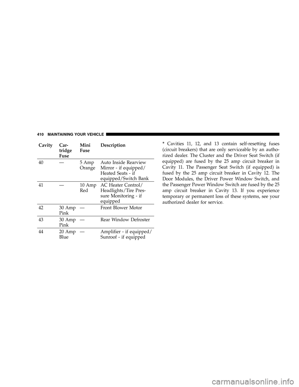
Sunroof - if equipped*Cavities 11, 12, and 13 contain self-resetting fuses
(circuit breakers) that are only serviceable by an autho-
rized dealer. The Cluster and the Driver Seat Switch (if
equipped) are fused by the 25 amp circuit breaker in
Cavity 11. The Passenger Seat Switch (if equipped) is
fused by the 25 amp circuit breaker in Cavity 12. The
Door Modules, the Driver Power Window Switch, and
the Passenger Power Window Switch are fused by the 25
amp circuit breaker in Cavity 13. If you experience
temporary or permanent loss of these systems, see your
authorized dealer for service.
410 MAINTAINING YOUR VEHICLE
Page 411 of 466
CAUTION!
²When installing the Power Distribution Center
cover, it is important to ensure the cover is prop-
erly positioned and fully latched. Failure to do so
may allow water to get into the Power Distribution
Center, and possibly result in an electrical system
failure.
²When replacing a blown fuse, it is important to
use only a fuse having the correct amperage rating.
The use of a fuse with a rating other than indicated
may result in a dangerous electrical system over-
load. If a properly rated fuse continues to blow, it
indicates a problem in the circuit that must be
corrected.
VEHICLE STORAGE
If you are leaving your vehicle dormant for more than 21
days, you may want to take steps to protect your battery.
You may:
²Disconnect the negative cable from the battery.
²Anytime you store your vehicle, or keep it out of
service (i.e. vacation) for two weeks or more, run the
air conditioning system at idle for about five minutes
in the fresh air and high blower setting. This will
insure adequate system lubrication to minimize the
possibility of compressor damage when the system is
started again.
MAINTAINING YOUR VEHICLE 411
7
Page 412 of 466

REPLACEMENT LIGHT BULBS
LIGHT BULBS Ð Interior Bulb Number
Rear Courtesy/Reading Lights.............. W5W
Rear Compartment (Trunk) Light............. 562
Overhead Console Reading Lights............. 578
Visor Vanity Lights.....................A6220
Glove Box Light......................... 194
Door Courtesy.......................... 562
Shift Indicator Light.................JKLE14140
Optional Door Map Pocket /
Cup Holder Lighting....... LED(Serviced at Dealer)
NOTE:For lighted switches, see your dealer for replace-
ment instructions.
All of the interior bulbs are glass wedge base or glass
cartridge types. Aluminum base bulbs are not approved
and should not be used for replacement.LIGHT BULBS Ð Exterior Bulb Number
Low Beam Headlight.....................9006
High Beam Headlight.....................9005
Front Park/Turn Light...................3157A
Front Fog LightÐ
If Equipped..........9145/H10 (Serviced at Dealer)
Front Side Marker.......... 194(Serviced at Dealer)
Tail/Stop Light.........................3057
Tail/Turn Light.........................3057
Rear Side Marker........................ 168
Backup Light........................... 921
Center High Mount Stop Light
(CHMSL)............... LED(Serviced at Dealer)
License................................ 168
412 MAINTAINING YOUR VEHICLE
Page 426 of 466
EMISSION CONTROL SYSTEM MAINTENANCE
The ªScheduledº maintenance services, listed inbold
typemust be done at the times or mileages specified to
assure the continued proper functioning of the emission
control system. These, and all other maintenance services
included in this manual, should be done to provide best
vehicle performance and reliability. More frequent main-
tenance may be needed for vehicles in severe operating
conditions such as dusty areas and very short trip
driving.
Inspection and service also should be done any time a
malfunction is suspected.
NOTE:Maintenance, replacement, or repair of the emis-
sion control devices and systems on your vehicle may be
performed by any automotive repair establishment or
individual using any automotive part, which has been
certified pursuant to U.S. EPA or, in the State of Califor-
nia, California Air Resources Board regulations.
MAINTENANCE SCHEDULE
The oil change indicator system will remind you that it is
time to take your vehicle in for scheduled maintenance.
On Electronic Vehicle Information Center (EVIC)
equipped vehicles, ªOil Change Requiredº will be dis-
played in the EVIC and a single chime will sound,
indicating that an oil change is necessary.
On Non-EVIC equipped vehicles, ªChange Oilº will flash
in the instrument cluster odometer and a single chime
will sound, indicating that an oil change is necessary.
Based on engine operation conditions the oil change
indicator message will illuminate, this means that service
is required for your vehicle. Have your vehicle serviced
as soon as possible, within the next 500 miles (805 km).
426 MAINTENANCE SCHEDULES
8
M
A
I
N
T
E
N
A
N
C
E
S
C
H
E
D
U
L
E
S