2008 CHRYSLER TOWN AND COUNTRY change wheel
[x] Cancel search: change wheelPage 245 of 531
ELECTRONIC VEHICLE INFORMATION CENTER
(EVIC) Ð IF EQUIPPED
NOTE:The compass on your vehicle is self-calibrating,
eliminating the need to manually calibrate the compass.
The Electronic Vehicle Information Center (EVIC) fea-
tures a driver-interactive display that is located in the
instrument cluster.
This system conveniently allows the driver to select a
variety of useful information by pressing the switches
mounted on the steering wheel. The EVIC consists of the
following:
²System Status display
²Vehicle information warning message displays
²Tire Pressure Monitor System
²Personal Settings (Customer Programmable Features)
²Compass display
²Outside temperature display
²Trip computer functions
²Audio Modes display
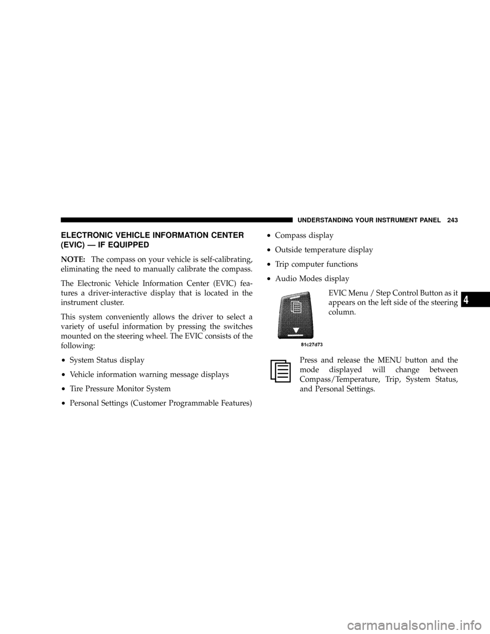
EVIC Menu / Step Control Button as it
appears on the left side of the steering
column.
Press and release the MENU button and the
mode displayed will change between
Compass/Temperature, Trip, System Status,
and Personal Settings.
UNDERSTANDING YOUR INSTRUMENT PANEL 243
4
Page 246 of 531

Press the STEP button to scroll through sub
menus (i.e. Trip Functions, Avg. Fuel Economy,
DTE, Elapsed Time, and Units.
Steering Wheel EVIC Compass/Temp
Control Button as it appears on the
right side of the steering column
Press and release the C/T button to for instant
access to the Compass/Temperature Screens.
Press this button to RESET Trip Functions and
Change Personal Settings.EVIC Displays
When the appropriate conditions exist, the EVIC displays
the following messages:
²Door(s) Ajar (with a single chime if vehicle is in
motion)
²Liftgate Ajar (chime will sound when vehicle starts
moving)
²Hood Ajar (If equipped with hood switch)
²Check TPM System. Refer to ªTire Pressure Monitor-
ing Systemº in Section 5 of this manual.
²Turn Signal On
²RKE Battery Low
²LOW WASHER FLUID
²Oil Change Required
²Left Front Turn Signal Light Out
244 UNDERSTANDING YOUR INSTRUMENT PANEL
Page 255 of 531
you understand and save you concern about these ªap-
parentº malfunctions, you must understand a point or
two about the transmission and reception of radio sig-
nals.
Two Types of Signals
There are two basic types of radio signals:
1. AM or Amplitude Modulation, in which the transmit-
ted sound causes the amplitude, or height, of the radio
waves to vary.
2. FM or Frequency Modulation, in which the frequency
of the wave is varied to carry the sound.
AM Reception
AM sound is based on wave amplitude, so AM reception
can be disrupted by such things as lightning, power lines
and neon signs.
FM Reception
Because FM transmission is based on frequency varia-
tions, interference that consists of amplitude variations
can be filtered out, leaving the reception relatively clear,
which is the major feature of FM radio.
NOTE:The radio, steering wheel radio controls (if
equipped), and six-disc CD/DVD changer (if equipped)
will remain active for up to 90 seconds after the ignition
switch has been turned OFF, depending upon the EVIC,
Accessory Delay setting. Opening a vehicle front door
will cancel this feature.
Electrical Disturbances
Radio waves may pick up electrical disturbances during
transmission. They mainly affect the wave amplitude,
and thus remain a part of the AM reception. They
interfere very little with the frequency variations that
carry the FM signal.
UNDERSTANDING YOUR INSTRUMENT PANEL 253
4
Page 369 of 531
WARNING!
²DO NOT use a tire, wheel size or rating other than that
specified for your vehicle. Some combinations of un-
approved tires and wheels may change suspension
dimensions and performance characteristics, resulting
in changes to steering, handling, and braking of your
vehicle. This can cause unpredictable handling and
stress to steering and suspension components. You
could lose control and have an accident resulting in
serious injury or death. Use only the tire and wheel
sizes with load ratings approved for your vehicle.
²NEVER use a tire with a smaller load index or capacity,
other than what was originally equipped on your
vehicle. Using a tire with a smaller load index could
result in tire overloading and failure. You could lose
control and have an accident.
²Failure to equip your vehicle with tires having ad-
equate speed capability can result in sudden tire fail-
ure and loss of vehicle control.
CAUTION!
Replacing original tires with tires of a different size
may result in false speedometer and odometer
readings.
Alignment and Tire Balance
Poor suspension alignment may result in:
²Fast tire wear.
²Uneven tire wear, such as feathering and one-sided
wear.
²Vehicle pull to right or left.
Tires may also cause the vehicle to pull to the left or right.
Alignment will not correct this condition. See your
authorized dealer for proper diagnosis.
STARTING AND OPERATING 367
5
Page 374 of 531
CAUTION!
After inspecting or adjusting the tire pressure always
reinstall the valve stem cap. This will prevent mois-
ture and dirt from entering the valve stem, which
could damage the TPMS SENSOR.
NOTE:
²The TPMS is not intended to replace normal tire care
and maintenance, or to provide warning of a tire
failure or condition.
²The TPMS should not be used as a tire pressure gauge
while adjusting your tire pressure.
²Driving on a significantly under-inflated tire causes
the tire to overheat and can lead to tire failure.
Under-inflation also reduces fuel efficiency and tire
tread life, and may affect the vehicle's handling and
stopping ability.
²The TPMS is not a substitute for proper tire mainte-
nance, and it is the driver's responsibility to maintain
correct tire pressure, using an accurate tire pressure
gage, even if under-inflation has not reached the level
to trigger illumination of the TPMS Warning Lamp.
NOTE:Seasonal temperature changes will affect tire
pressure, and the TPMS will monitor the actual tire
pressure in the tire.
BASIC TPMS WITHOUT EVIC Ð IF EQUIPPED
The TPMS uses wireless technology with wheel rim
mounted electronic sensors to monitor tire pressure lev-
els. Sensors, mounted to each wheel as part of the valve
stem, transmit tire pressure readings to the Receiver
Module.
NOTE:It is particularly important, for you to check the
tire pressure in all of your tires regularly and to maintain
the proper pressure.
372 STARTING AND OPERATING
Page 418 of 531
WARNING!
Carefully follow these tire changing warnings to help
prevent personal injury or damage to your vehicle:
²Never start or run the engine with the vehicle on a
jack.
²Do not let anyone sit in the vehicle when it is on a
jack.
²Do not get under the vehicle when it is on a jack.
²Only use the jack in the positions indicated and for
lifting this vehicle during a tire change.
²If working on or near a roadway, be extremely
careful of motor traffic.
²To assure that spare tires, flat or inflated are securely
stowed, spares must be stowed with the valve stem
facing the ground.
²Turn on the Hazard warning flasher.
1. Loosen (but do not remove) the wheel lug nuts by
turning them to the left one turn while the wheel is still
on the ground.
2. To remove the compact spare tire/cover assembly,
assemble the winch handle extensions to form a ªT' and
fit the winch ªTº handle over the drive nut. Rotate the
nut to the left until the winch mechanism stops turning
freely. This will allow enough slack in the cable to allow
you to pull the spare tire out from under the vehicle.
CAUTION!
The winch mechanism is designed for use with the
winch ªTº handle only. Use of an air wrench or other
power tools is not recommended and can damage the
winch.
416 WHAT TO DO IN EMERGENCIES
Page 424 of 531
of operation, and after each time a tire is changed, to
allow the wheel nuts to become properly set. All nuts
should first be firmly seated against the wheel. The nuts
should then be tightened to recommended torque.
Tighten the nuts to final torque in increments. Progress
around the bolt circle, tightening the nut opposite to the
nut just previously tightened until final torque is
achieved. Recommended torque is 95 ft lbs (130 N´m).
Secure The Spare Tire As Follows:
1. To stow the compact spare tire/cover assembly on
vehicles equipped with Stow 'n Go seating, assemble the
winch handle extensions to form a ªT' and fit the winch
ªTº handle over the drive nut. Rotate the nut to the left
until the winch mechanism stops turning freely. This will
allow enough slack in the cable to allow you to pull the
wheel spacer out from under the vehicle.
WARNING!
A loose compact spare tire/cover assembly, thrown
forward in a collision or hard stop could endanger
the occupants of the vehicle. Always stow the com-
pact spare tire with the cover assembly in the place
provided.
CAUTION!
The winch mechanism is designed for use with the
winch ªTº handle only. Use of an air wrench or other
power tools is not recommended and can damage the
winch.
422 WHAT TO DO IN EMERGENCIES
Page 467 of 531
If the fluid level indicates low, add sufficient fluid to
bring to the proper level.
CAUTION!
Do not overfill. Dirt and water in the transaxle can
cause serious damage. To prevent dirt and water from
entering the transaxle after checking or replenishing
fluid, make certain that the dipstick cap is reseated
properly.
Fluid and Filter Changes
Refer to the ªMaintenance Scheduleº in Section 8 of this
manual for the recommended transaxle fluid and filter
change intervals.
If the transaxle is disassembled for any reason, the fluid
and filter should be changed.
Special Additives
Automatic Transmission Fluid (ATF) is an engineered
product and its performance may be impaired by supple-
mental additives. Therefore, do not add any fluid addi-
tives to the transaxle. The only exception to this policy is
the use of special dyes to aid in detecting fluid leaks. In
addition, avoid using transaxle sealers as they may
adversely affect seals.
FRONT AND REAR WHEEL BEARINGS
Front and rear wheel bearings are permanently sealed.
No regular maintenance is required for these compo-
nents.
APPEARANCE CARE AND PROTECTION FROM
CORROSION
Protection of Body and Paint from Corrosion
Vehicle body care requirements vary according to geo-
graphic locations and usage. Chemicals that make roads
passable in snow and ice, and those that are sprayed on
MAINTAINING YOUR VEHICLE 465
7