2008 CHRYSLER TOWN AND COUNTRY flat tire
[x] Cancel search: flat tirePage 375 of 531
The Basic TPMS consists of the following components:
²Receiver Module
²Four Wheel Sensors
²TPMS Telltale Warning Light
The TPMS Telltale Warning Light will illumi-
nate in the instrument cluster, and an audible
chime will be activated when one or more of
the four active road tire pressures are low.
Should this occur, you should stop as soon as possible,
check the inflation pressure of each tire on your vehicle,
and inflate each tire to the vehicle's recommended cold
tire pressure value (located on the placard on the
driver's-side B-Pillar). The system will automatically
update and the TPMS Warning Lamp will extinguish
once the updated tire pressures have been received.NOTE:The vehicle may need to be driven for up to 10
minutes above 15 mph (25 km/h) to receive this infor-
mation.
The TPMS Warning Lamp will flash on and off for 75
seconds, and remain on sold when a system fault is
detected. The system fault will also sound a chime. If the
ignition key is cycled, this sequence will repeat, provid-
ing the system fault still exists. The TPMS Warning Lamp
will turn off when the fault condition no longer exists. A
system fault can occur with any of the following sce-
narios:
1. Jamming due to electronic devices or driving next to
facilities emitting the same radio frequencies as the TPMS
sensors.
2. Installing some form of aftermarket window tinting
that affects radio wave signals.
STARTING AND OPERATING 373
5
Page 378 of 531
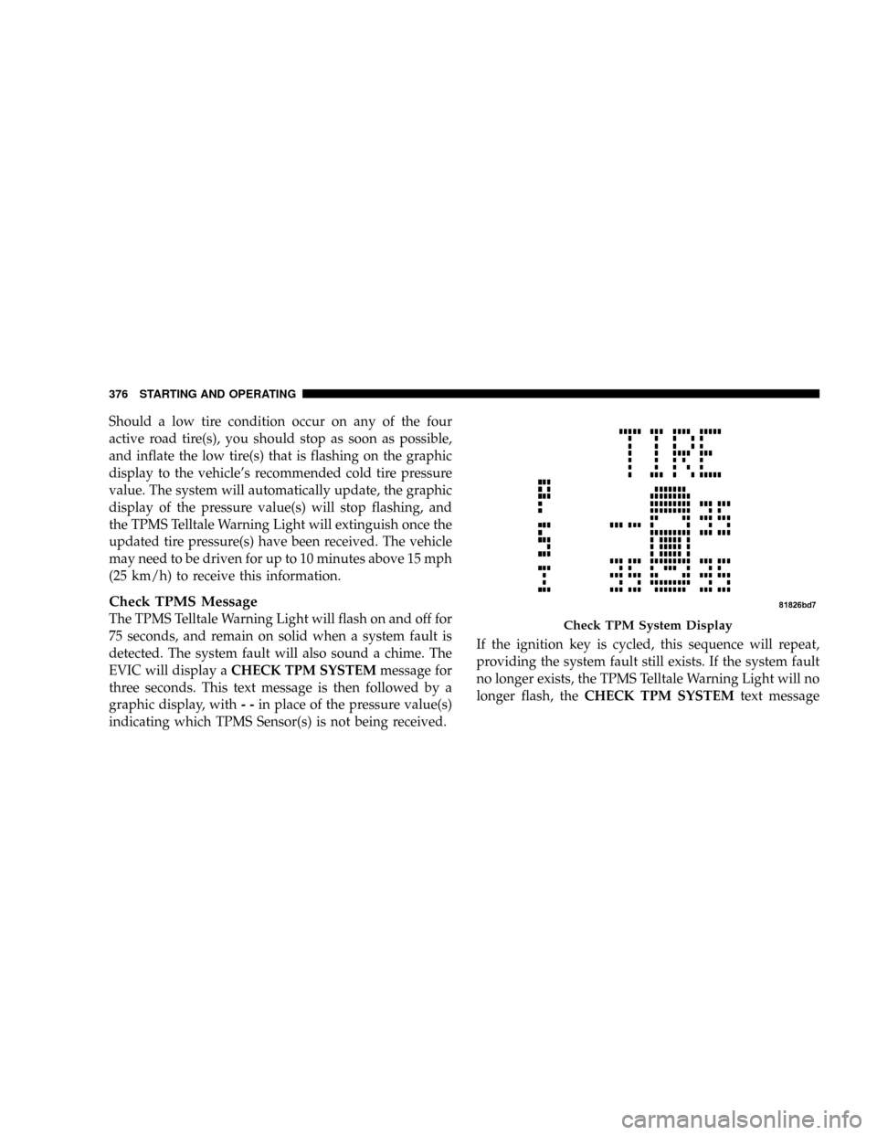
Should a low tire condition occur on any of the four
active road tire(s), you should stop as soon as possible,
and inflate the low tire(s) that is flashing on the graphic
display to the vehicle's recommended cold tire pressure
value. The system will automatically update, the graphic
display of the pressure value(s) will stop flashing, and
the TPMS Telltale Warning Light will extinguish once the
updated tire pressure(s) have been received. The vehicle
may need to be driven for up to 10 minutes above 15 mph
(25 km/h) to receive this information.
Check TPMS Message
The TPMS Telltale Warning Light will flash on and off for
75 seconds, and remain on solid when a system fault is
detected. The system fault will also sound a chime. The
EVIC will display aCHECK TPM SYSTEMmessage for
three seconds. This text message is then followed by a
graphic display, with--in place of the pressure value(s)
indicating which TPMS Sensor(s) is not being received.If the ignition key is cycled, this sequence will repeat,
providing the system fault still exists. If the system fault
no longer exists, the TPMS Telltale Warning Light will no
longer flash, theCHECK TPM SYSTEMtext messageCheck TPM System Display
376 STARTING AND OPERATING
Page 393 of 531

Gross Vehicle Weight Rating (GVWR)
The GVWR is the total allowable weight of your vehicle.
This includes driver, passengers, and cargo. The total
load must be limited so that you do not exceed the
GVWR.
Gross Axle Weight Rating (GAWR)
The GAWR is the maximum capacity of the front and rear
axles. Distribute the load over the front and rear axles
evenly. Make sure that you do not exceed either front or
rear GAWR.
WARNING!
Because the front wheels drive and steer the vehicle,
it is important that you do not exceed the maximum
front or rear GAWR. A dangerous driving condition
can result if either rating is exceeded. You could lose
control of the vehicle and have an accident.
Tire Size
The tire size on the Vehicle Certification Label represents
the actual tire size on your vehicle. Replacement tires
must be equal to the load capacity of this tire size.
Rim Size
This is the rim size that is appropriate for the tire size
listed.
Inflation Pressure
This is the cold tire inflation pressure for your vehicle for
all loading conditions up to full GAWR.
Curb Weight
The curb weight of a vehicle is defined as the total weight
of the vehicle with all fluids, including vehicle fuel, at full
capacity conditions, and with no occupants or cargo
loaded into the vehicle. The front and rear curb weight
values are determined by weighing your vehicle on a
commercial scale before any occupants or cargo are
added.
STARTING AND OPERATING 391
5
Page 405 of 531
4. Trailer tongue weight rating for that trailer hitch.
(This requirement may limit the ability to always
achieve the 10% to 15% range of trailer tongue weight
as a percentage of total trailer weight.)
Towing Requirements Ð Tires
²
Do not attempt to tow a trailer while using a compact
spare tire.
²Proper tire inflation pressures are essential to the safe
and satisfactory operation of your vehicle. Refer to the
Tires±General Information section of this manual on
Tire Pressures for proper tire inflation procedures.
²Also, check the trailer tires for proper tire inflation
pressures before trailer usage.
²Check for signs of tire wear or visible tire damage
before towing a trailer. Refer to the Tires±General
Information section of this manual on Tread Wear
Indicators for the proper inspection procedure.
²When replacing tires refer to the Tires±General Infor-
mation section of this manual on Replacement Tires
for proper tire replacement procedures. Replacing tires
with a higher load carrying capacity will not increase
the vehicle's GVWR and GAWR limits.
Towing Requirements Ð Trailer Brakes
²
Donotinterconnect the hydraulic brake system or
vacuum system of your vehicle with that of the trailer.
This could cause inadequate braking and possible
personal injury.
²An electronically actuated trailer brake controller is
required when towing a trailer with electronically
actuated brakes. When towing a trailer equipped with
a hydraulic surge actuated brake system, an electronic
brake controller is not required.
²Trailer brakes are recommended for trailers over 1,000
lbs (454 kg) and required for trailers in excess of 2,000
lbs (907 kg).
STARTING AND OPERATING 403
5
Page 418 of 531
WARNING!
Carefully follow these tire changing warnings to help
prevent personal injury or damage to your vehicle:
²Never start or run the engine with the vehicle on a
jack.
²Do not let anyone sit in the vehicle when it is on a
jack.
²Do not get under the vehicle when it is on a jack.
²Only use the jack in the positions indicated and for
lifting this vehicle during a tire change.
²If working on or near a roadway, be extremely
careful of motor traffic.
²To assure that spare tires, flat or inflated are securely
stowed, spares must be stowed with the valve stem
facing the ground.
²Turn on the Hazard warning flasher.
1. Loosen (but do not remove) the wheel lug nuts by
turning them to the left one turn while the wheel is still
on the ground.
2. To remove the compact spare tire/cover assembly,
assemble the winch handle extensions to form a ªT' and
fit the winch ªTº handle over the drive nut. Rotate the
nut to the left until the winch mechanism stops turning
freely. This will allow enough slack in the cable to allow
you to pull the spare tire out from under the vehicle.
CAUTION!
The winch mechanism is designed for use with the
winch ªTº handle only. Use of an air wrench or other
power tools is not recommended and can damage the
winch.
416 WHAT TO DO IN EMERGENCIES
Page 419 of 531
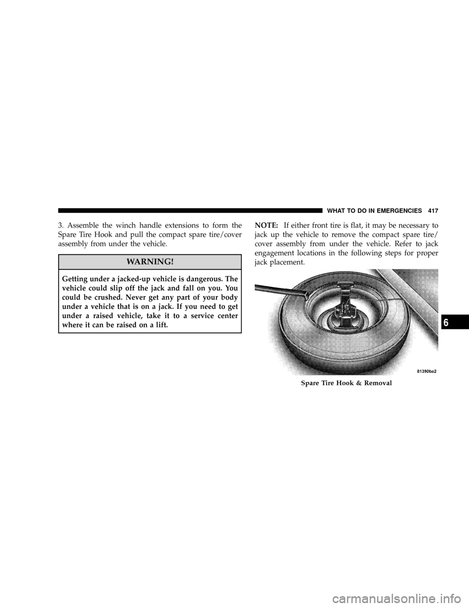
3. Assemble the winch handle extensions to form the
Spare Tire Hook and pull the compact spare tire/cover
assembly from under the vehicle.
WARNING!
Getting under a jacked-up vehicle is dangerous. The
vehicle could slip off the jack and fall on you. You
could be crushed. Never get any part of your body
under a vehicle that is on a jack. If you need to get
under a raised vehicle, take it to a service center
where it can be raised on a lift.NOTE:If either front tire is flat, it may be necessary to
jack up the vehicle to remove the compact spare tire/
cover assembly from under the vehicle. Refer to jack
engagement locations in the following steps for proper
jack placement.
Spare Tire Hook & Removal
WHAT TO DO IN EMERGENCIES 417
6
Page 423 of 531
10. Lower the vehicle by turning the jack screw to the
left.
11. Finish tightening the lug nuts. Push down on the
wrench while tightening for increased leverage. Alternate
lug nuts until each nut has been tightened twice. Correct
wheel nut tightness is 95 ft lbs (130 N´m). If in doubt
about the correct tightness, have them checked with a
torque wrench by your authorized dealer or at a service
station.
12. Lower the jack to its fully-closed position.
WARNING!
A loose tire or jack thrown forward in a collision or
hard stop could endanger the occupants of the ve-
hicle. Always stow the jack parts and the spare tire in
the places provided. Have the deflated (flat) tire
repaired or replaced immediately.13. Place the deflated (flat) tire and compact spare tire
cover assembly in the rear cargo area.Do not stow the
deflated tire in the spare tire location.Have the full
sized tire repaired or replaced as soon as possible.
14. Stow the cable and wheel spacer before driving the
vehicle. Reassemble the winch handle extensions to form
a ªT' and fit the winch ªTº handle over the drive nut.
Rotate the nut to the right until the winch mechanism
clicks at least three times.
15. Stow the jack, jack handle and winch handle tools.
16. Check the compact spare tire pressure as soon as
possible. Correct pressure as required.Wheel Nuts
All wheel nuts should be tightened occasionally to elimi-
nate the possibility of wheel studs being sheared or the
bolt holes in the wheels becoming elongated. This is
especially important during the first few hundred miles
WHAT TO DO IN EMERGENCIES 421
6
Page 426 of 531
CAUTION!
For vehicles equipped with Stow 'n Go seating, the
Winch Mechanism is designed specifically to stow a
COMPACT Spare Tire ONLY. Do not attempt to use
the Winch to stow the Full Size 'Flat' Tire, or any
other Full Size Tire. Vehicle damage may result.
JUMP-STARTING PROCEDURE
WARNING!
²DO NOT attempt to push or tow the vehicle to get it started. Vehicles
equipped with an automatic transmission cannot be started this way.
Unburned fuel could enter the catalytic converter and once the engine
has started, ignite and damage the converter and vehicle.
²If the vehicle has a discharged battery, booster cables may be used to
obtain a start from another vehicle. This type of start can be dangerous
if done improperly, so follow this procedure carefully.
²Battery fluid is a corrosive acid solution; DO NOT allow battery fluid to
contact eyes, skin or clothing. Don't lean over battery when attaching
clamps or allow the clamps to touch each other. If acid splashes in the
eyes or on the skin, flush the contaminated area immediately with large
quantities of water.
²A battery generates hydrogen gas which is flammable and explosive. Keep
all flames or sparks away from the vent holes. DO NOT use a booster
battery or any other booster source with an output that exceeds 12 volts.
²During cold weather when temperatures are below freezing point, elec-
trolyte in a discharged battery may freeze. DO NOT attempt jump-starting
because the battery could rupture or explode. The battery temperature
must be brought up above freezing point before attempting jump-start.
²Take special care to avoid the radiator cooling fan whenever the hood is
raised. The cooling fan is electrically operated and can start anytime the
ignition switch is ON. You can be hurt by the fan.
424 WHAT TO DO IN EMERGENCIES