Page 420 of 531
4. When the compact spare tire/cover assembly is clear
of the vehicle, stand the tire/cover assembly upright and
remove the wheel spacer by squeezing the two retaining
tabs together.5. There are two jack engagement locations on each side
of the vehicle body. These locations are on the sill flange
of the vehicle body.
NOTE:Rear jack location is between a pair of down-
standing tabs on the sill flange of the vehicle body.
Front jack location is on the sill flange of the vehicle body
and aligns with the front door edge.
Squeezing Winch Retainer Tabs
418 WHAT TO DO IN EMERGENCIES
Page 422 of 531
CAUTION!
Do not attempt to raise the vehicle by jacking on
locations other than those indicated in Step 5.
6. Place the wrench on the jack screw and turn to the
right until the jack head is properly engaged in the
described location.Do not raise the vehicle until you are
sure the jack is securely engaged.
7. Raise the vehicle by turning the jack screw to the right,
using the swivel wrench. Raise the vehicle only until the
tire just clears the surface and enough clearance is
obtained to install the spare tire. Minimum tire lift
provides maximum stability.
WARNING!
Raising the vehicle higher than necessary can make
the vehicle less stable. It could slip off the jack and
hurt someone near it. Raise the vehicle only enough
to remove the tire.
8. Remove the wheel lug nuts, for vehicles with wheel
covers, remove the cover from the wheel by hand. Do not
pry the wheel cover off. Then pull the wheel off the hub.
9. Install the compact spare tire. Lightly tighten the lug
nuts. To avoid the risk of forcing the vehicle off the jack,
do not tighten the lug nuts fully until the vehicle has been
lowered.
NOTE:Do not install the wheel cover on the compact
spare.
Do not use a hammer or force to install the wheel covers.
420 WHAT TO DO IN EMERGENCIES
Page 423 of 531
10. Lower the vehicle by turning the jack screw to the
left.
11. Finish tightening the lug nuts. Push down on the
wrench while tightening for increased leverage. Alternate
lug nuts until each nut has been tightened twice. Correct
wheel nut tightness is 95 ft lbs (130 N´m). If in doubt
about the correct tightness, have them checked with a
torque wrench by your authorized dealer or at a service
station.
12. Lower the jack to its fully-closed position.
WARNING!
A loose tire or jack thrown forward in a collision or
hard stop could endanger the occupants of the ve-
hicle. Always stow the jack parts and the spare tire in
the places provided. Have the deflated (flat) tire
repaired or replaced immediately.13. Place the deflated (flat) tire and compact spare tire
cover assembly in the rear cargo area.Do not stow the
deflated tire in the spare tire location.Have the full
sized tire repaired or replaced as soon as possible.
14. Stow the cable and wheel spacer before driving the
vehicle. Reassemble the winch handle extensions to form
a ªT' and fit the winch ªTº handle over the drive nut.
Rotate the nut to the right until the winch mechanism
clicks at least three times.
15. Stow the jack, jack handle and winch handle tools.
16. Check the compact spare tire pressure as soon as
possible. Correct pressure as required.Wheel Nuts
All wheel nuts should be tightened occasionally to elimi-
nate the possibility of wheel studs being sheared or the
bolt holes in the wheels becoming elongated. This is
especially important during the first few hundred miles
WHAT TO DO IN EMERGENCIES 421
6
Page 424 of 531
of operation, and after each time a tire is changed, to
allow the wheel nuts to become properly set. All nuts
should first be firmly seated against the wheel. The nuts
should then be tightened to recommended torque.
Tighten the nuts to final torque in increments. Progress
around the bolt circle, tightening the nut opposite to the
nut just previously tightened until final torque is
achieved. Recommended torque is 95 ft lbs (130 N´m).
Secure The Spare Tire As Follows:
1. To stow the compact spare tire/cover assembly on
vehicles equipped with Stow 'n Go seating, assemble the
winch handle extensions to form a ªT' and fit the winch
ªTº handle over the drive nut. Rotate the nut to the left
until the winch mechanism stops turning freely. This will
allow enough slack in the cable to allow you to pull the
wheel spacer out from under the vehicle.
WARNING!
A loose compact spare tire/cover assembly, thrown
forward in a collision or hard stop could endanger
the occupants of the vehicle. Always stow the com-
pact spare tire with the cover assembly in the place
provided.
CAUTION!
The winch mechanism is designed for use with the
winch ªTº handle only. Use of an air wrench or other
power tools is not recommended and can damage the
winch.
422 WHAT TO DO IN EMERGENCIES
Page 425 of 531
2. Assemble the winch handle extensions to form the
Spare Tire Hook and pull the wheel spacer from under
the vehicle.
3. Turn the compact spare tire so that the valve stem is
down and place the tire into the spare tire cover assem-
bly. Slide the wheel spacer through the center of the
wheel and spare tire cover assembly so that the two
retainer tabs snap out and engage the spare tire cover on
the opposite side.
CAUTION!
The compact spare tire cover assembly must be used
when the compact spare tire is stored. Failure to use
this cover could drastically reduce the life of the
compact spare tire.
WARNING!
Verify that 'both' retainer tabs of the wheel spacer
have been properly extended through the center of
the wheel and spare tire cover assembly. Failure to
properly engage both retainer tabs could result in
loss of the spare tire & cover assembly, which will
cause vehicle damage and may cause loss of control
of the vehicle.
4. Using the winch ªTº handle, rotate the drive nut to the
right until the compact spare tire/cover assembly is
drawn into place against the underside of the vehicle.
5. Continue to rotate the nut to the right until you hear
the winch mechanism click three times. It cannot be
overtightened. Check under the vehicle to ensure the
compact spare tire/cover assembly is positioned cor-
rectly against the underside of the vehicle.
WHAT TO DO IN EMERGENCIES 423
6
Page 525 of 531

Sentry Key Programming................... 17
Sentry Key Replacement................... 16
Service Assistance....................... 499
Service Contract......................... 501
Service Engine Soon Light
(Malfunction Indicator).................... 233
Service Manuals........................ 504
Setting the Clock................255,271,283,286
Settings, Personal........................ 249
Shoulder Belts........................... 56
Signals, Turn...................165,229,482,484
Sliding Door............................ 41
Slippery Surfaces, Driving On............... 348
Snow Chains (Tire Chains)................. 368
Snow Tires............................ 369
Sound Systems (Radio).................282,285
Spare Tire.......................362,364,413
Spark Plugs............................ 443
Speed Control (Cruise Control).............. 177Speedometer........................... 229
Starting............................... 326
Automatic Transmission................. 327
Cold Weather......................... 327
Engine Fails to Start.................... 328
Remote.............................. 27
Starting and Operating.................... 326
Starting Procedures...................... 326
Steering
Column Controls...................... 165
Linkage............................. 451
Power...........................347,451
Shaft Seal............................ 451
Tilt Column.......................... 169
Steering Wheel Mounted Sound System
Controls.............................. 300
Storage............................206,479
Storage Bin............................ 206
Storage, Vehicle......................320,479
INDEX 523
10
Page 527 of 531
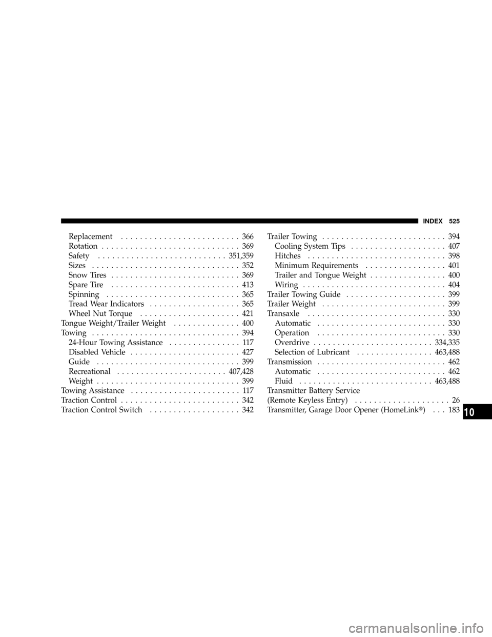
Replacement......................... 366
Rotation............................. 369
Safety...........................351,359
Sizes............................... 352
Snow Tires........................... 369
Spare Tire........................... 413
Spinning............................ 365
Tread Wear Indicators................... 365
Wheel Nut Torque..................... 421
Tongue Weight/Trailer Weight.............. 400
Towing............................... 394
24-Hour Towing Assistance............... 117
Disabled Vehicle....................... 427
Guide.............................. 399
Recreational.......................407,428
Weight.............................. 399
Towing Assistance....................... 117
Traction Control......................... 342
Traction Control Switch................... 342Trailer Towing.......................... 394
Cooling System Tips.................... 407
Hitches............................. 398
Minimum Requirements................. 401
Trailer and Tongue Weight................ 400
Wiring.............................. 404
Trailer Towing Guide..................... 399
Trailer Weight.......................... 399
Transaxle............................. 330
Automatic........................... 330
Operation........................... 330
Overdrive.........................334,335
Selection of Lubricant................463,488
Transmission........................... 462
Automatic........................... 462
Fluid............................463,488
Transmitter Battery Service
(Remote Keyless Entry).................... 26
Transmitter, Garage Door Opener (HomeLinkt)... 183
INDEX 525
10