Page 29 of 531

General Information
This device complies with part 15 of the FCC rules and
RSS 210 of Industry Canada. Operation is subject to the
following conditions:
²This device may not cause harmful interference.
²This device must accept any interference received,
including interference that may cause undesired op-
eration.
If your RKE transmitter fails to operate from a normal
distance, check for these two conditions.
1. A weak battery in the RKE transmitter. The expected
life of the battery is a minimum of three years.
2. Closeness to a radio transmitter such as a radio station
tower, airport transmitter, and some mobile or CB radios.
REMOTE STARTING SYSTEM Ð IF EQUIPPED
Remote Starting conveniently starts the engine from
outside the vehicle by using the Remote Keyless Entry
(RKE) transmitter while maintaining the Security Alarm
System. The Remote Starting System has a targeted range
of 328 ft (100 m). In order to Remote Start your vehicle,
the hood, liftgate, and all the doors must be closed and
the transmission gear selector lever in PARK.
NOTE:Remote Starting requires automatic transaxle-
equipped vehicles.
THINGS TO KNOW BEFORE STARTING YOUR VEHICLE 27
2
Page 95 of 531

A new engine may consume some oil during its first few
thousand miles (kilometers) of operation. This should be
considered as a normal part of the break-in and not
interpreted as an indication of difficulty.
SAFETY TIPS
SAFETY CHECKS YOU SHOULD MAKE INSIDE
THE VEHICLE
Seat Belts
Inspect the belt system periodically checking for cuts,
frays, and loose parts. Damaged parts must be replaced
immediately. Do not disassemble or modify the system.
Front seat belt assemblies must be replaced after a
collision. Rear seat belt assemblies must be replaced after
a collision if they have been damaged (bent retractor, torn
webbing, etc.). If there is any question regarding belt or
retractor condition, replace the belt.
Airbag Light
The light should come on and remain on for four seconds
as a bulb check when the ignition switch is first turned
ON. If the LED is not lit during starting and/or the light
stays on or comes ON while driving, have the system
checked by an authorized dealer.
Defroster
Check operation by selecting the defrost mode and place
the blower control on high speed. You should be able to
feel the air directed against the windshield.
NOTE:If the defroster is not working or you are unable
to feel air against the windshield in defrost mode, please
see your authorized dealer service center for repairs.
THINGS TO KNOW BEFORE STARTING YOUR VEHICLE 93
2
Page 224 of 531
mRadio Operation And Cellular Phones........300
mRemote Sound System Controls Ð If Equipped . . 300
NRadio Operation......................301
NCD Player..........................301
mCD/DVD Maintenance...................301
mClimate Controls.......................302
NManual Heating, Ventilation And Air
Conditioning (HVAC) System.............302
NRear Manual Climate Control Zone Ð
If Equipped.........................308
NAutomatic Temperature Control (ATC) Ð
If Equipped.........................311NSummer Operation....................319
NWinter Operation.....................319
NVacation/Storage.....................320
NWindow Fogging.....................320
NOutside Air Intake....................320
NOperating Tips.......................321
NA/C Air Filter Ð If Equipped............321
mElectric Rear Window Defroster Ð
If Equipped...........................321
222 UNDERSTANDING YOUR INSTRUMENT PANEL
Page 235 of 531

19. Malfunction Indicator Light
This light is part of an onboard diagnostic system
called OBD that monitors engine and automatic
transmission control systems. The light will illu-
minate when the key is in the ON position before engine
start. If the bulb does not come on when turning the key
from OFF to ON, have the condition checked promptly.
Certain conditions such as a loose or missing gas cap,
poor fuel quality, etc. may illuminate the light after
engine start. The vehicle should be serviced if the light
stays on through several of your typical driving cycles. In
most situations the vehicle will drive normally and will
not require towing.
If the Malfunction Indicator Light flashes when the
engine is running, serious conditions may exist that
could lead to immediate loss of power or severe catalytic
converter damage. The vehicle should be serviced as
soon as possible if this occurs.20. Airbag Light
This light turns on and remains on for seven
seconds as a bulb check when the ignition
switch is first turned ON. If the light is not on
during starting, stays on, or turns on while
driving, have the system inspected by an authorized
dealer as soon as possible.
21. Temperature Gauge
The temperature gauge shows engine coolant tem-
perature. Any reading within the normal range
indicates that the engine cooling system is operat-
ing satisfactorily.
The gauge pointer will likely indicate a higher tempera-
ture when driving in hot weather, up mountain grades,
or when towing a trailer. It should not be allowed to
exceed the upper limits of the normal operating range.
UNDERSTANDING YOUR INSTRUMENT PANEL 233
4
Page 236 of 531

CAUTION!
Driving with a hot engine cooling system could
damage your vehicle. If temperature gauge reads
ªHª, pull over and stop the vehicle. Idle the vehicle
with the air conditioner turned off until the pointer
drops back into the normal range. If the pointer
remains on the ªHº, and you hear continuous chimes,
turn the engine off immediately, and call your autho-
rized dealership for service.
WARNING!
A hot engine cooling system is dangerous. You or
others could be badly burned by steam or boiling
coolant. You may want to call an authorized dealer-
ship for service if your vehicle overheats. If you
decide to look under the hood yourself, see Section 7
of this manual. Follow the warnings under the Cool-
ing System Pressure Cap paragraph.
22. Trip/Odometer Display Reset Button Ð Base
Cluster
To reset a trip odometer, display the trip odometer to be
reset then push and hold the button until the display
resets (approximately two seconds). The odometer must
be in TRIP mode to reset it.
234 UNDERSTANDING YOUR INSTRUMENT PANEL
Page 304 of 531
2. If a disc is stained, clean the surface with a soft cloth,
wiping from center to edge.
3. Do not apply paper, paper CD labels, or tape to the
disc; avoid scratching a disc.
4. Do not use solvents such as benzine, thinner, cleaners,
or antistatic sprays.
5. Store a disc in its case after playing.
6. Do not expose a disc to direct sunlight.
7. Do not store a disc where temperatures may become
too high.
8. Do not play discs that are small in size or have
irregular shapes.CLIMATE CONTROLS
The Climate Control System allows you to regulate the
temperature, amount, and direction of air circulating
throughout the vehicle. The controls are located on the
instrument panel, below the radio.
MANUAL HEATING, VENTILATION AND AIR
CONDITIONING (HVAC) SYSTEM
The controls for the manual HVAC system in this vehicle
consist of a series of outer rotary dials inner push knobs.
These comfort controls can be set to obtain desired
interior conditions.
302 UNDERSTANDING YOUR INSTRUMENT PANEL
Page 306 of 531

NOTE:If your air conditioning performance seems
lower than expected, check the front of the A/C con-
denser (located in front of the radiator), for an accumu-
lation of dirt or insects. Clean with a gentle water spray
from behind the radiator and through the condenser.
Fabric front fascia protectors may reduce airflow to the
condenser, reducing air conditioning performance.
Mode Control (Air Direction)
Mode control allows you to choose
from several patterns of air distribu-
tion. You can select either a primary
mode, as identified by the symbols, or
a blend of two of these modes. The
closer the control is to a particular
mode, the more air distribution you
receive from that mode.
PANEL Mode
Air is directed through the outlets in the instrument
panel. These outlets can be adjusted to direct airflow.
BI-LEVEL Mode
Air is directed through the panel and floor outlets.
NOTE:There is a difference in temperature (in any
conditions other than full cold or full hot), between the
upper and lower outlets for added comfort. The warmer
air goes to the floor outlets. This feature gives improved
comfort during sunny but cool conditions.
FLOOR Mode
Air is directed through the floor outlets with a
small amount through the defrost and side window
demist outlets.
304 UNDERSTANDING YOUR INSTRUMENT PANEL
Page 307 of 531

MIX Mode
Air is directed through the floor, defrost and side
window demist outlets. This setting works best in
cold or snowy conditions that require extra heat at
the windshield. This setting is good for maintaining
comfort while reducing moisture on the windshield.
DEFROST Mode
Air is directed through the windshield and side
window demist outlets. Use DEFROST mode with
maximum blower and temperature settings for best
windshield and side window defrosting.
NOTE:The air conditioning compressor operates in
MIX and DEFROST, or a blend of these modes even if the
A/C SNOWFLAKE button is not pressed. This dehu-
midifies the air to help dry the windshield. To improve
fuel economy, use these modes only when necessary.
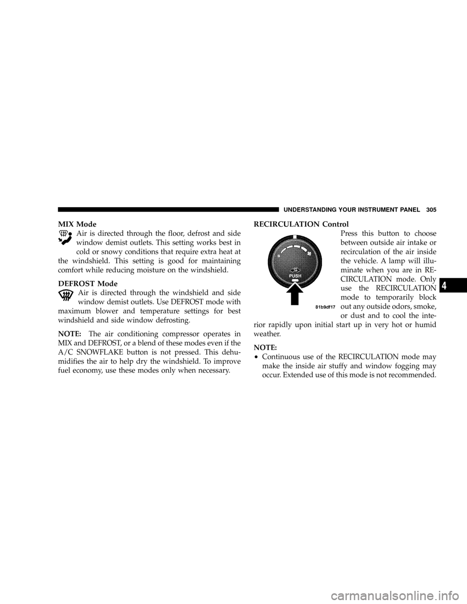
RECIRCULATION Control
Press this button to choose
between outside air intake or
recirculation of the air inside
the vehicle. A lamp will illu-
minate when you are in RE-
CIRCULATION mode. Only
use the RECIRCULATION
mode to temporarily block
out any outside odors, smoke,
or dust and to cool the inte-
rior rapidly upon initial start up in very hot or humid
weather.
NOTE:
²Continuous use of the RECIRCULATION mode may
make the inside air stuffy and window fogging may
occur. Extended use of this mode is not recommended.
UNDERSTANDING YOUR INSTRUMENT PANEL 305
4