2008 CHRYSLER SEBRING SEDAN sensor
[x] Cancel search: sensorPage 183 of 494

NOTE:Please note that the TPMS is not a substitute for
proper tire maintenance, and it is the driver ’s responsi-
bility to maintain correct tire pressure, even if under-
inflation has not reached the level to trigger illumination
of the TPMS low tire pressure telltale.
Your vehicle has also been equipped with a TPMS
malfunction indicator to indicate when the system is not
operating properly. The TPMS malfunction indicator is
combined with the low tire pressure telltale. When the
system detects a malfunction, the telltale will flash for
approximately one minute and then remain continuously
illuminated. This sequence will continue upon subse-
quent vehicle start-ups as long as the malfunction exists.
When the malfunction indicator is illuminated, the sys-
tem may not be able to detect or signal low tire pressure
as intended. TPMS malfunctions may occur for a variety
of reasons, including the installation of replacement or
alternate tires or wheels on the vehicle that prevent the
TPMS from functioning properly. Always check theTPMS malfunction telltale after replacing one or more
tires or wheels on your vehicle to ensure that the replace-
ment or alternate tires and wheels allow the TPMS to
continue to function properly.
CAUTION!
The TPMS has been optimized for the original
equipment tires and wheels. TPMS pressures and
warning have been established for the tire size
equipped on your vehicle. Undesirable system opera-
tion or sensor damage may result when using re-
placement equipment that is not of the same size,
type, and/or style. Aftermarket wheels can cause
sensor damage. Do not use aftermarket tire sealants
or balance beads if your vehicle is equipped with a
TPMS, as damage to the sensors may result.
UNDERSTANDING YOUR INSTRUMENT PANEL 181
4
Page 191 of 494

Compass Variance
Compass Variance is the difference between magnetic
North and Geographic North. In some areas of the
country, the difference between magnetic and geographic
North is great enough to cause the compass to give false
readings. If this occurs, the compass variance must be set
using the following procedure:
NOTE:Magnetic materials and cell phones should be
kept away from the top of the Instrument Panel. This is
where the compass sensor is located.
UNDERSTANDING YOUR INSTRUMENT PANEL 189
4
Page 251 of 494

accomplish this, the system gathers information from the
cabin infrared sensor mounted between the sun-visors
and from various sensors located throughout the vehicle.
The controls on the climate control provide the system
with operator input. Other sensors take account of ve-
hicle speed, A/C pressure, outside temperature, and
engine cooling temperature. Using all of these inputs, the
system automatically adjusts airflow temperature, air-
flow distribution, airflow volume, and the amount of
outside air recirculation. This maintains a comfortable
temperature even under changing conditions.
Operation of the system is quite simple.
1. Turn the Mode Control knob (on the right) and the
Blower Control knob (on the left) to AUTO.
NOTE:The AUTO position performs best for front seat
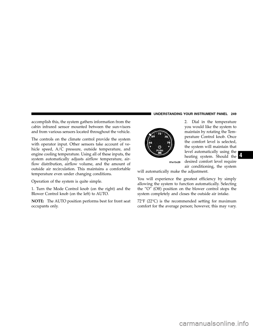
occupants only.2. Dial in the temperature
you would like the system to
maintain by rotating the Tem-
perature Control knob. Once
the comfort level is selected,
the system will maintain that
level automatically using the
heating system. Should the
desired comfort level require
air conditioning, the system
will automatically make the adjustment.
You will experience the greatest efficiency by simply
allowing the system to function automatically. Selecting
the “O” (Off) position on the blower control stops the
system completely and closes the outside air intake.
72°F (22°C) is the recommended setting for maximum
comfort for the average person; however, this may vary.
UNDERSTANDING YOUR INSTRUMENT PANEL 249
4
Page 289 of 494

Electronic Stability Program (ESP)
This system enhances directional control and stability of
the vehicle under various driving conditions. ESP cor-
rects for over/under steering of the vehicle by applying
the brake of the appropriate wheel to assist in counter-
acting the over/under steer condition. Engine power
may also be reduced to help the vehicle maintain the
desired path. ESP uses sensors in the vehicle to determine
the vehicle path intended by the driver and compares it
to the actual path of the vehicle. When the actual path
does not match the intended path, ESP applies the brake
of the appropriate wheel to assist in counteracting the
oversteer or understeer condition
•Oversteer - when the vehicle is turning more than
appropriate for the steering wheel position.
•Understeer - when the vehicle is turning less than
appropriate for the steering wheel position.
ESP/TCS Indicator Light
The “ESP/TCS Indicator Light,” located in the instru-
ment cluster, starts to flash as soon as the tires lose
traction and the ESP system becomes active. The “ESP/
TCS Indicator Light” also flashes when TCS is active. If
the “ESP/TCS Indicator Light” begins to flash during
acceleration, ease up on the accelerator and apply as little
throttle as possible. Be sure to adapt your speed and
driving to the prevailing road conditions.
STARTING AND OPERATING 287
5
Page 317 of 494

once the system receives the updated tire pressures.
The vehicle may need to be driven for up to 10 minutes
above 15 mph (25 km/h) in order for the TPMS to
receive this information.
�For example, your vehicle may have a recom-
mended cold (parked for more than 3 hours) placard
pressure of 30 psi (207 kPa). If the ambient tempera-
ture is 68°F (20°C) and the measured tire pressure is
27 psi (186 kPa), a temperature drop to 20°F (-7°C)
will decrease the tire pressure to approximately 23
psi (157 kPa). This tire pressure is sufficiently low
enough to turn ON the Tire Pressure Monitoring
Telltale light. Driving the vehicle may cause the tire
pressure to rise to approximately 27 psi (186 kPa),
but the Tire Pressure Monitoring Telltale Light will
still be ON. In this situation, the Tire Pressure
Monitoring Telltale Light will turn OFF only after
the tires are inflated to the vehicle’s recommended
cold placard pressure value.
CAUTION!
•The TPMS has been optimized for the original
equipment tires and wheels. TPMS pressures and
warning have been established for the tire size
equipped on your vehicle. Undesirable system op-
eration or sensor damage may result when using
replacement equipment that is not of the same size,
type, and/or style. Aftermarket wheels can cause
sensor damage. Do not use aftermarket tire sealants
or balance beads if your vehicle is equipped with a
TPMS, as damage to the sensors may result.
•After inspecting or adjusting the tire pressure,
always reinstall the valve stem cap. This will
prevent moisture and dirt from entering the valve
stem, which could damage the Tire Pressure Moni-
toring Sensor.
STARTING AND OPERATING 315
5
Page 318 of 494

NOTE:
•The TPMS is not intended to replace normal tire care
and maintenance, or to provide warning of a tire
failure or condition.
•The TPMS should not be used as a tire pressure gauge
while adjusting your tire pressure.
•Driving on a significantly under-inflated tire causes
the tire to overheat and can lead to tire failure.
Under-inflation also reduces fuel efficiency and tire
tread life, and may affect the vehicle’s handling and
stopping ability.
•The TPMS is not a substitute for proper tire mainte-
nance, and it is the driver ’s responsibility to maintain
correct tire pressure using an accurate tire pressure
gauge, even if under-inflation has not reached the
level to trigger illumination of the Tire Pressure Moni-
toring Telltale light.
•Seasonal temperature changes will affect tire pressure,
and the TPMS will monitor the actual tire pressure in
the tire.
Base System — If Equipped
The Tire Pressure Monitor System (TPMS) uses wireless
technology with wheel rim mounted electronic sensors to
monitor tire pressure levels. Sensors, mounted to each
wheel as part of the valve stem, transmit tire pressure
readings to the Receiver Module.
NOTE:It is particularly important for you to check the
tire pressure in all of the tires on your vehicle monthly
and to maintain the proper pressure.
The TPMS consists of the following components:
•Receiver Module
•4 Tire Pressure Monitoring Sensors
•Tire Pressure Monitoring Telltale Light
316 STARTING AND OPERATING
Page 319 of 494

Tire Pressure Monitoring Low Pressure Warnings
The Tire Pressure Monitoring Telltale Light will
illuminate in the instrument cluster and a chime
will sound when tire pressure is low in one or
more of the four active road tires. Should this occur, you
should stop as soon as possible, check the inflation
pressure of each tire on your vehicle, and inflate each tire
to the vehicle’s recommended cold placard pressure
value. Once the system receives the updated tire pres-
sures, the system will automatically update and the Tire
Pressure Monitoring Telltale Light will turn off. The
vehicle may need to be driven for up to 10 minutes above
15 mph (25 km/h) in order for the TPMS to receive this
information.
Check TPMS Warning
The Tire Pressure Monitoring Telltale Light will flash on
and off for 75 seconds and then remain on solid when a
system fault is detected. The system fault will also sound
a chime. If the ignition key is cycled, this sequence willrepeat, providing the system fault still exists. The Tire
Pressure Monitoring Telltale Light will turn off when the
fault condition no longer exists. A system fault can occur
due to any of the following:
1. Jamming due to electronic devices or driving next to
facilities emitting the same Radio Frequencies as the TPM
sensors.
2. Installing some form of aftermarket window tinting
that affects radio wave signals.
3. Lots of snow or ice around the wheels or wheel
housings.
4. Using tire chains on the vehicle.
5. Using wheels/tires not equipped with TPM sensors.
STARTING AND OPERATING 317
5
Page 320 of 494

NOTE:
1. The compact spare tire (if so equipped) does not have
a tire pressure monitoring sensor. Therefore, the TPMS
will not monitor the pressure in the compact spare tire.
2. If you install the compact spare tire in place of a road
tire that has a pressure below the low-pressure warning
limit, upon the next ignition key cycle, a chime will
sound and the TPM Telltale Light will turn ON.
3. After driving the vehicle for up to 10 minutes above 15
mph (25 km/h), the TPM Telltale Light will flash on and
off for 75 seconds and then remain on solid.
4. For each subsequent ignition key cycle, a chime will
sound and the TPM Telltale Light will flash on and off for
75 seconds and then remain on solid.
5. Once you repair or replace the original road tire, and
reinstall it on the vehicle in place of the compact spare,
the TPMS will update automatically and the TPM TelltaleLight will turn OFF, as long no tire pressure is below the
low-pressure warning limit in any of the four active road
tires. The vehicle may need to be driven for up to 10
minutes above 15 mph (25 km/h) in order for the TPMS
to receive this information.
Premium System — If Equipped
The Tire Pressure Monitor System (TPMS) uses wireless
technology with wheel rim mounted electronic sensors to
monitor tire pressure levels. Sensors, mounted to each
wheel as part of the valve stem, transmit tire pressure
readings to the Receiver Module.
NOTE:It is particularly important for you to check the
tire pressure in all of the tires on your vehicle monthly
and to maintain the proper pressure.
The TPMS consists of the following components:
•Receiver Module
•4 Tire Pressure Monitoring Sensors
318 STARTING AND OPERATING