2008 CHEVROLET TRAIL BLAZER fuses
[x] Cancel search: fusesPage 88 of 472
Testing the Alarm
To test the alarm:
1. From inside the vehicle, lower the driver’s window
and open the driver’s door.
2. Activate the system by locking the doors with the
power door lock switch while the door is open, or
with the RKE transmitter.
3. Get out of the vehicle, close the door and wait for
the security light to go out.
4. Then reach in through the window, unlock the door
with the manual door lock and open the door. This
should set off the alarm.
When the alarm is set the power door unlock switch will
not work.
If the alarm does not sound when it should but the
headlamps �ash, check to see if the horn works. The
horn fuse may be blown. To replace the fuse, seeFuses
and Circuit Breakers on page 5-110.
If the alarm does not sound or the headlamps do not
�ash, the vehicle should be serviced by your
dealer/retailer.
Passlock®(U. S. Only)
Your vehicle has the Passlock theft-deterrent system.
Passlock is a passive theft-deterrent system that
enables fuel if the ignition lock cylinder is turned with a
valid key. If a correct key is not used or the ignition
lock cylinder has been tampered with, the fuel system is
disabled and the vehicle will not start.
During normal operation, the security light will turn off
about �ve seconds after the key is turned to ON/RUN.
If the engine stalls and the security light �ashes,
wait about 10 minutes until the light stops �ashing before
trying to restart the engine. Remember to release the
key from START as soon as the engine starts.
If the engine does not start after three tries, the vehicle
needs service.
If the engine is running and the security light comes on,
you will be able to restart the engine if you turn the
engine off. However, your Passlock system is not
working properly and must be serviced by your
dealer/retailer. Your vehicle is not protected by Passlock
at this time. You may also want to check the fuse.
SeeFuses and Circuit Breakers on page 5-110. See
your dealer/retailer for service.
In an emergency, call the Roadside Assistance Center.
SeeRoadside Assistance Program on page 7-7.
Do not leave the key or device that disarms or
deactivates the theft deterrent system in the vehicle.
2-16
Page 90 of 472
If the engine still does not start, and the key appears to
be undamaged, try another ignition key. At this time,
you may also want to check the fuse. SeeFuses
and Circuit Breakers on page 5-110. If the engine still
does not start with the other key, your vehicle needs
service. If your vehicle does start, the �rst key may be
faulty. See your dealer/retailer who can service the
theft-deterrent system and have a new key made.
It is possible for the theft-deterrent system decoder to
learn the transponder value of a new or replacement
key. Up to 10 keys may be programmed for the vehicle.
The following procedure is for programming additional
keys only.
Canadian Owners:If you lose or damage your keys,
only a dealer/retailer can service the theft-deterrent
system to have new keys made. To program additional
keys you will require two current driver’s keys.
To program a new key do the following:
1. Verify that the new key has PK3+ stamped on it.
2. Insert the current driver’s key in the ignition
and start the engine. If the engine will not start see
your dealer/retailer for service.3. After the engine has started, turn the key to
LOCK/OFF, and remove the key.
4. Insert the second current driver’s key in the ignition
and start the engine within ten seconds of removing
the previous key. If the engine will not start see
your dealer/retailer for service.
5. After the engine has started, turn the key to
LOCK/OFF, and remove the key. Insert the key to
be programmed and turn it to ON within ten
seconds of removing the previous key.
The security light will turn off once the key has
been programmed.
6. Repeat the Steps 1 through 5 if additional keys are
to be programmed.
If the security light comes on and stays on while driving,
you will be able to restart the engine if you turn it off.
The theft-deterrent system, however, is not working
properly and must be serviced by your dealer/retailer.
Your vehicle is not protected by the theft-deterrent
system at this time.
In an emergency, contact Roadside Assistance. See
Roadside Assistance Program on page 7-7.
Do not leave the key or device that disarms or
deactivates the theft deterrent system in the vehicle.
2-18
Page 137 of 472
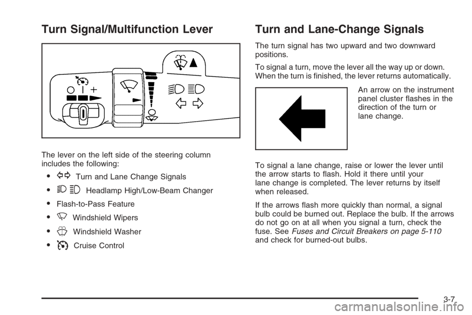
Turn Signal/Multifunction Lever
The lever on the left side of the steering column
includes the following:
GTurn and Lane Change Signals
23Headlamp High/Low-Beam Changer
Flash-to-Pass Feature
NWindshield Wipers
JWindshield Washer
ICruise Control
Turn and Lane-Change Signals
The turn signal has two upward and two downward
positions.
To signal a turn, move the lever all the way up or down.
When the turn is �nished, the lever returns automatically.
An arrow on the instrument
panel cluster �ashes in the
direction of the turn or
lane change.
To signal a lane change, raise or lower the lever until
the arrow starts to �ash. Hold it there until your
lane change is completed. The lever returns by itself
when released.
If the arrows �ash more quickly than normal, a signal
bulb could be burned out. Replace the bulb. If the arrows
do not go on at all when you signal a turn, check the
fuse. SeeFuses and Circuit Breakers on page 5-110
and check for burned-out bulbs.
3-7
Page 150 of 472
Accessory Power Outlet(s)
With the accessory power outlets, you can plug in
auxiliary electrical equipment such as a cellular
telephone or CB radio.
Your vehicle has three accessory power outlets.
There are two outlets located below the climate controls
and one outlet is on the rear of the center �oor console.
Remove the cover from the outlet to use the outlet.
Be sure to put the cover back on when not using the
accessory power outlet.
Certain electrical accessories may not be compatible
with the accessory power outlet and could result
in blown vehicle or adaptor fuses. If you experience a
problem, see your dealer for additional information
on the accessory power outlets.Notice:Adding any electrical equipment to the
vehicle can damage it or keep other components
from working as they should. The repairs would not
be covered by the vehicle warranty. Do not use
equipment exceeding maximum amperage rating of
20 amperes. Check with your dealer/retailer before
adding electrical equipment.
When adding electrical equipment, be sure to follow
the proper installation instructions included with
the equipment.
Notice:Improper use of the power outlet can cause
damage not covered by your warranty. Do not
hang any type of accessory or accessory bracket
from the plug because the power outlets are
designed for accessory power plugs only.
3-20
Page 300 of 472
Tire Pressure Monitor Operation.....................5-69
Tire Inspection and Rotation...........................5-72
When It Is Time for New Tires.......................5-74
Buying New Tires.........................................5-75
Different Size Tires and Wheels......................5-77
Uniform Tire Quality Grading..........................5-78
Wheel Alignment and Tire Balance..................5-80
Wheel Replacement......................................5-80
Tire Chains..................................................5-82
Accessory In�ator.........................................5-82
If a Tire Goes Flat........................................5-84
Changing a Flat Tire.....................................5-85
Removing the Spare Tire and Tools................5-86
Removing the Flat Tire and Installing the
Spare Tire................................................5-89
Secondary Latch System...............................5-94
Storing a Flat or Spare Tire and Tools............5-97
Spare Tire.................................................5-100
Appearance Care..........................................5-100
Interior Cleaning.........................................5-100
Fabric/Carpet..............................................5-101
Leather......................................................5-102
Instrument Panel, Vinyl, and Other Plastic
Surfaces.................................................5-103
Care of Safety Belts....................................5-103Weatherstrips.............................................5-103
Washing Your Vehicle..................................5-104
Cleaning Exterior Lamps/Lenses....................5-104
Finish Care................................................5-104
Windshield, Backglass, and Wiper Blades.......5-105
Aluminum Wheels.......................................5-106
Tires.........................................................5-106
Sheet Metal Damage...................................5-106
Finish Damage...........................................5-107
Underbody Maintenance...............................5-107
Chemical Paint Spotting...............................5-107
Vehicle Care/Appearance Materials................5-108
Vehicle Identi�cation.....................................5-109
Vehicle Identi�cation Number (VIN)................5-109
Service Parts Identi�cation Label...................5-109
Electrical System..........................................5-109
Add-On Electrical Equipment.........................5-109
Headlamps.................................................5-110
Windshield Wiper Fuses...............................5-110
Power Windows and Other Power Options......5-110
Fuses and Circuit Breakers..........................5-110
Engine Compartment Fuse Block...................5-111
Rear Underseat Fuse Block..........................5-118
Capacities and Speci�cations........................5-121
Section 5 Service and Appearance Care
5-2
Page 408 of 472
Headlamps
The headlamp wiring is protected by four fuses. An
electrical overload will cause a lamp to go on and off.
If this happens, have your headlamp wiring checked
right away.
Windshield Wiper Fuses
The windshield wiper motor is protected by a circuit
breaker and a fuse. If the motor overheats due to heavy
snow, etc., the wiper will stop until the motor cools. If the
overload is caused by some electrical problem, have
it �xed.
Power Windows and Other Power
Options
Circuit breakers in the fuse block protect the power
windows and other power accessories. When the current
load is too heavy, the circuit breaker opens and closes,
protecting the circuit until the problem is �xed or
goes away.
Fuses and Circuit Breakers
The wiring circuits in your vehicle are protected from
short circuits by a combination of fuses and circuit
breakers. This greatly reduces the chance of �res
caused by electrical problems.
Look at the silver-colored band inside the fuse. If the
band is broken or melted, replace the fuse. Be sure you
replace a bad fuse with a new one of the identical size
and rating.
If you ever have a problem on the road and don’t have
a spare fuse, you can borrow one that has the same
amperage. Just pick some feature of your vehicle
that you can get along without — like the radio or
cigarette lighter — and use its fuse, if it is the correct
amperage. Replace it as soon as you can.
5-110
Page 410 of 472
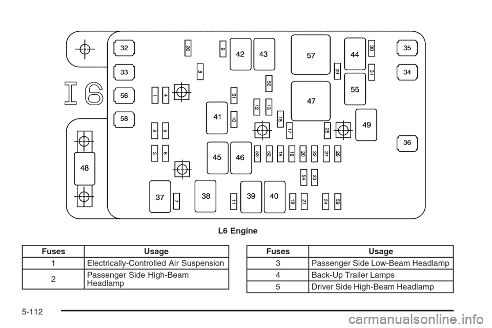
Fuses Usage
1 Electrically-Controlled Air Suspension
2Passenger Side High-Beam
HeadlampFuses Usage
3 Passenger Side Low-Beam Headlamp
4 Back-Up Trailer Lamps
5 Driver Side High-Beam Headlamp L6 Engine
5-112
Page 411 of 472
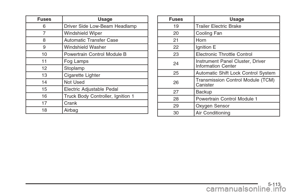
Fuses Usage
6 Driver Side Low-Beam Headlamp
7 Windshield Wiper
8 Automatic Transfer Case
9 Windshield Washer
10 Powertrain Control Module B
11 Fog Lamps
12 Stoplamp
13 Cigarette Lighter
14 Not Used
15 Electric Adjustable Pedal
16 Truck Body Controller, Ignition 1
17 Crank
18 AirbagFuses Usage
19 Trailer Electric Brake
20 Cooling Fan
21 Horn
22 Ignition E
23 Electronic Throttle Control
24Instrument Panel Cluster, Driver
Information Center
25 Automatic Shift Lock Control System
26Transmission Control Module (TCM)
Canister
27 Backup
28 Powertrain Control Module 1
29 Oxygen Sensor
30 Air Conditioning
5-113