2008 CHEVROLET AVALANCHE auxiliary battery
[x] Cancel search: auxiliary batteryPage 275 of 528

Using the Auxiliary Input Jack
The radio system has an auxiliary input jack located on
the lower right side of the faceplate. This is not an
audio output; do not plug the headphone set into the
front auxiliary input jack. An external audio device such
as an iPod, laptop computer, MP3 player, CD player,
or cassette tape player, etc. can be connected to
the auxiliary input jack for use as another audio source.
Drivers are encouraged to set up any auxiliary device
while the vehicle is in PARK (P). SeeDefensive Driving
on page 4-2for more information on driver distraction.
To use a portable audio player, connect a 3.5 mm
(1/8 inch) cable to the radio’s front auxiliary input jack.
When a device is connected, press the radio CD/AUX
button to begin playing audio from the device over
the vehicle speakers.
For optimal sound quality, increase the portable audio
device’s volume to the loudest level.
It is always best to power the portable audio device
through its own battery while playing.
O(Power/Volume):Turn clockwise or
counterclockwise to increase or decrease the volume of
the portable player. Additional volume adjustments
might have to be made from the portable device if the
volume is not loud or soft enough.BAND:Press to listen to the radio when a portable
audio device is playing. The portable audio device also
continues to play.
CD/AUX (CD/Auxiliary):Press to play a CD when a
portable audio device is playing. Press again and
the system begins playing audio from the connected
portable audio player. If a portable audio player is
not connected, “No Input Device Found” displays.
DVD/CD AUX (CD/Auxiliary):Press this button to cycle
through DVD, CD, or Auxiliary when listening to the radio.
The DVD/CD text label and a message showing track or
chapter number displays when a disc is in either slot.
Press this button again and the system automatically
searches for an auxiliary input device, such as a portable
audio player. If a portable audio player is not connected,
“No Aux Input Device” displays. If a disc is in both the
DVD slot and the CD slot the DVD/CD AUX button cycles
between the two sources and does not indicate “No Aux
Input Device”. If a front auxiliary device is connected, the
DVD/CD AUX button cycles through all available options,
such as: DVD slot, CD slot, Front Auxiliary, and Rear
Auxiliary (if available). See “Using the Auxiliary Input
Jack(s)” later in this section, or “Audio/Video (A/V) Jacks”
under,Rear Seat Entertainment (RSE) System on
page 3-107for more information.
3-95
Page 288 of 528

Headphones
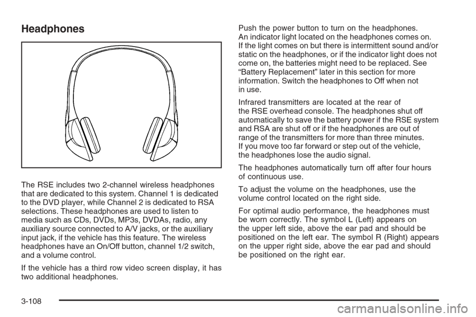
The RSE includes two 2-channel wireless headphones
that are dedicated to this system. Channel 1 is dedicated
to the DVD player, while Channel 2 is dedicated to RSA
selections. These headphones are used to listen to
media such as CDs, DVDs, MP3s, DVDAs, radio, any
auxiliary source connected to A/V jacks, or the auxiliary
input jack, if the vehicle has this feature. The wireless
headphones have an On/Off button, channel 1/2 switch,
and a volume control.
If the vehicle has a third row video screen display, it has
two additional headphones.Push the power button to turn on the headphones.
An indicator light located on the headphones comes on.
If the light comes on but there is intermittent sound and/or
static on the headphones, or if the indicator light does not
come on, the batteries might need to be replaced. See
“Battery Replacement” later in this section for more
information. Switch the headphones to Off when not
in use.
Infrared transmitters are located at the rear of
the RSE overhead console. The headphones shut off
automatically to save the battery power if the RSE system
and RSA are shut off or if the headphones are out of
range of the transmitters for more than three minutes.
If you move too far forward or step out of the vehicle,
the headphones lose the audio signal.
The headphones automatically turn off after four hours
of continuous use.
To adjust the volume on the headphones, use the
volume control located on the right side.
For optimal audio performance, the headphones must
be worn correctly. The symbol L (Left) appears on
the upper left side, above the ear pad and should be
positioned on the left ear. The symbol R (Right) appears
on the upper right side, above the ear pad and should
be positioned on the right ear.
3-108
Page 289 of 528

Notice:Do not store the headphones in heat or
direct sunlight. This could damage the headphones
and repairs will not be covered by your warranty.
Storage in extreme cold can weaken the batteries.
Keep the headphones stored in a cool, dry place.
If the foam ear pads attached to the headphones
become worn or damaged, the pads can be replaced
separately from the headphone set. See your
dealer/retailer for more information.
Battery Replacement
To change the batteries on the headphones, do the
following:
1. Turn the screw to loosen the battery door located
on the left side of the headphones. Slide the
battery door open.
2. Replace the two batteries in the compartment.
Make sure that they are installed correctly, using the
diagram on the inside of the battery compartment.
3. Replace the battery door and tighten the
door screw.
If the headphones are to be stored for a long period of
time, remove the batteries and keep them in a cool,
dry place.
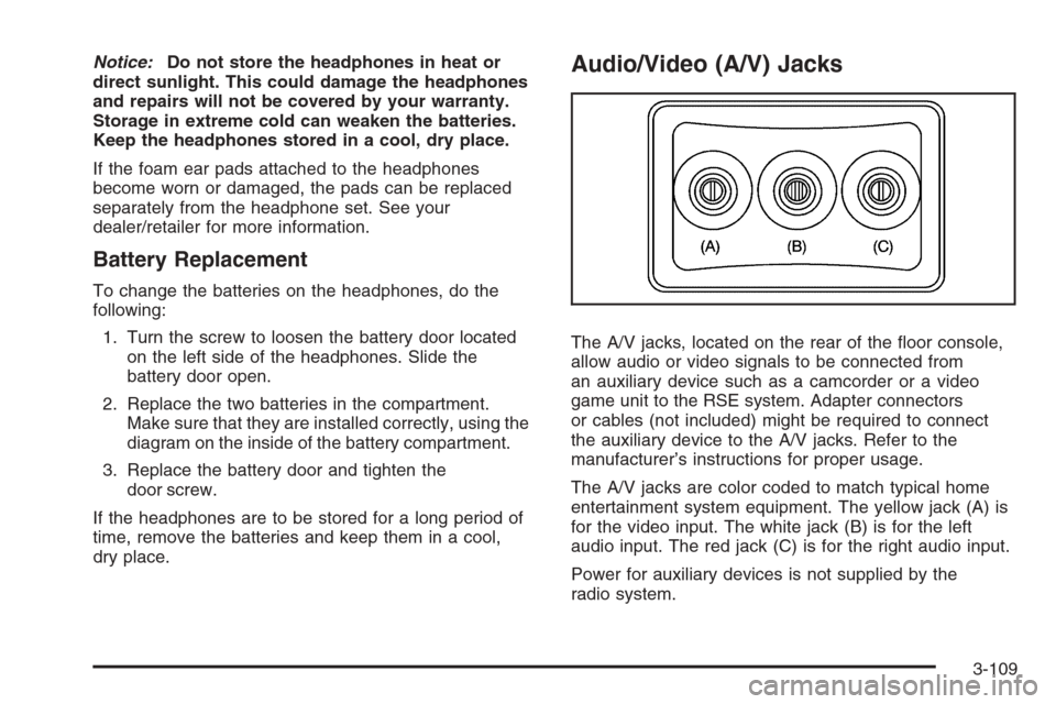
Audio/Video (A/V) Jacks
The A/V jacks, located on the rear of the �oor console,
allow audio or video signals to be connected from
an auxiliary device such as a camcorder or a video
game unit to the RSE system. Adapter connectors
or cables (not included) might be required to connect
the auxiliary device to the A/V jacks. Refer to the
manufacturer’s instructions for proper usage.
The A/V jacks are color coded to match typical home
entertainment system equipment. The yellow jack (A) is
for the video input. The white jack (B) is for the left
audio input. The red jack (C) is for the right audio input.
Power for auxiliary devices is not supplied by the
radio system.
3-109
Page 294 of 528

\(Clear):Press this button within three seconds after
entering a numeric selection, to clear all numerical inputs.
}10 (Double Digit Entries):Press this button to
select chapter or track numbers greater than nine.
Press this button before entering the number.
If the remote control becomes lost or damaged, a new
universal remote control can be purchased. If this
happens, make sure the universal remote control
uses a code set of Toshiba
®.
Battery Replacement
To change the remote control batteries, do the following:
1. Slide the rear cover back on to the remote control.
2. Replace the two batteries in the compartment.
Make sure that they are installed correctly, using
the diagram on the inside of the battery
compartment.
3. Replace the battery cover.
If the remote control is to be stored for a long period of
time, remove the batteries and keep them in a cool,
dry place.
Problem Recommended Action
No power. The ignition might not be
turned ON/RUN or in
ACC/ACCESSORY.
The picture does not �ll
the screen. There are
black borders on the
top and bottom or on
both sides or it looks
stretched out.Check the display mode
settings in the setup menu
by pressing the display
menu button on the remote
control.
In auxiliary mode, the
picture moves or scrolls.Check the auxiliary input
connections at both
devices.
The remote control does
not work.Check to make sure there
is no obstruction between
the remote control and
the transmitter window.
Check the batteries to
make sure they are not
dead or installed
incorrectly.
After stopping the player,
I push Play but sometimes
the DVD starts where I left
off and sometimes at the
beginning.If the stop button was
pressed one time, the DVD
player resumes playing
where the DVD was
stopped. If the stop button
was pressed two times the
DVD player begins to play
from the beginning of
the DVD.
3-114
Page 360 of 528

Electric Brake Control Wiring
Provisions
These wiring provisions are included with your vehicle
as part of the heavy-duty trailer wiring package.
These provisions are for an electric brake controller.
The instrument panel contains blunt cut wires near
the data link connector for the trailer brake controller.
The harness contains the following wires:
Dark Blue: Auxiliary
Red/Black: Battery
Light Blue: Brake Switch
White: Ground
The trailer brake controller should be installed by your
dealer/retailer or a quali�ed service center.
Trailer Recommendations
You must subtract your hitch loads from the Cargo
Weight Rating (CWR). CWR is the maximum weight
of the load your vehicle can carry. It doesn’t include the
weight of the people inside, but you can �gure about
150 lbs. (68 kg) for each seat. The total cargo load
must not be more than your vehicles CWR.
Weigh your vehicle with your trailer attached, so that
you won’t go over the GVWR or GAWR. If you are using
a weight-distributing hitch, weigh the vehicle without
the spring bars in place.
You’ll get the best performance if you spread out the
weight of your load the right way, and if you choose the
correct hitch and trailer brakes.
For more information seeTowing a Trailer on page 4-47.
4-60
Page 473 of 528

Fuses Usage
24Fuel Injectors, Ignition Coils
(Left Side)
25 Trailer Park Lamps
26 Driver Side Park Lamps
27 Passenger Side Park Lamps
28 Fog Lamps
29 Horn
30Passenger Side High-Beam
Headlamp
31 Daytime Running Lamps
32 Driver Side High-Beam Headlamp
33 Daytime Running Lights 2
34 Sunroof
35Key Ignition System, Theft Deterrent
System
36 Windshield Wiper
37 SEO B2 Up�tter Usage (Battery)
38 Electric Adjustable Pedals
39 Climate Controls (Battery)
40 Airbag System (Ignition)
41 Ampli�erFuses Usage
42 Audio System
43Miscellaneous (Ignition),
Cruise Control
44 Liftgate Release
45 Airbag System (Battery)
46 Instrument Panel Cluster
47 Power Take-Off
48Auxiliary Climate Control (Ignition),
Compass-Temperature Mirror
49 Center High-Mounted Stoplamp
50 Rear Defogger
51 Heated Mirrors
52 SEO B1 Up�tter Usage (Battery)
53Cigarette Lighter, Auxiliary Power
Outlet
54Automatic Level Control Compressor
Relay, SEO Up�tter Usage
55 Climate Controls (Ignition)
56Engine Control Module, Secondary
Fuel Pump (Ignition)
5-113