Page 4 of 165
Table of ContentsYou can also consult the in-
dex at the end of this Rider's
Manual if you want to find a
particular topic or item of in-
formation.
1 General instructions . . . 5
Overview . . . . . . . . . . . . . . . . . 6
Abbreviations and
symbols . . . . . . . . . . . . . . . . . . 6
Equipment . . . . . . . . . . . . . . . 7
Technical data . . . . . . . . . . . . 7
Currency . . . . . . . . . . . . . . . . . 7
2 General views . . . . . . . . . 9
General view, left side . . . 11
General view, right
side . . . . . . . . . . . . . . . . . . . . . 13
Underneath the seat . . . . . 15
Handlebar fitting, left . . . . . 16
Handlebar fitting, right . . . 17
Instrument cluster . . . . . . . 18
Headlight . . . . . . . . . . . . . . . 193 Status indicators . . . . . 21
Multifunction display . . . . . 22
Warning and telltale
lights . . . . . . . . . . . . . . . . . . . 22
ABS warning light
OE
..... 22
Function indicators . . . . . . 22
Warnings, general . . . . . . . 23
ABS warning
indicators . . . . . . . . . . . . . . . 30
4 Operation . . . . . . . . . . . . . 37
Ignition switch and
steering lock . . . . . . . . . . . . 38
Electronic immobiliser
(EWS) . . . . . . . . . . . . . . . . . . . 39
Hazard warning
flashers . . . . . . . . . . . . . . . . . 40
Tripmaster . . . . . . . . . . . . . . 41
On-board computerOE
... 43
Clock . . . . . . . . . . . . . . . . . . . 46
Emergency off switch (kill
switch) . . . . . . . . . . . . . . . . . . 47
Grip heating
OE
........... 47
Clutch . . . . . . . . . . . . . . . . . . 48
Brakes . . . . . . . . . . . . . . . . . . 48
Lights . . . . . . . . . . . . . . . . . . . 49 Headlight . . . . . . . . . . . . . . . 50
Turn indicators . . . . . . . . . . 50
Seat . . . . . . . . . . . . . . . . . . . . 51
Helmet holder . . . . . . . . . . . 53
Luggage loops . . . . . . . . . . 54
Mirrors . . . . . . . . . . . . . . . . . . 54
Spring preload . . . . . . . . . . 55
Shock absorbers . . . . . . . . 56
Electronic Suspension
Adjustment ESA
OE
....... 57
Tyres . . . . . . . . . . . . . . . . . . . 58
5 Riding . . . . . . . . . . . . . . . . 61
Safety instructions . . . . . . . 62
Checklist . . . . . . . . . . . . . . . . 64
Starting . . . . . . . . . . . . . . . . . 64
Pulling away with BMW
Integral ABS
OE
.......... 67
Running in . . . . . . . . . . . . . . 67
Parking your
motorcycle . . . . . . . . . . . . . . 71
Refuelling . . . . . . . . . . . . . . . 78
Brake system, general . . . 79
Brake system with BMW
Integral ABS
OE
.......... 79
Page 8 of 165
OverviewChapter 2 of this Rider's
Manual will provide you with
an initial overview of your
motorcycle. All maintenance
and servicing work on the
motorcycle is documented in
Chapter 10. This record of
the maintenance work you
have had performed on your
motorcycle is a precondition
for generous treatment of
claims submitted after the
warranty period has expired.
When the time comes to sell
your BMW, please remem-
ber to hand over this Rider's
Manual; it is an important part
of the motorcycle.
Abbreviations and
symbols
Indicates warnings that
you must comply with for
reasons of your safety and the
safety of others, and to pro-
tect your motorcycle against
damage.
Specific instructions on
how to operate, control,
adjust or look after items of
equipment on the motorcycle.
Indicates the end of an
item of information.
Instruction.
Result of an activity.
Reference to a page
with more detailed in-
formation. OE Optional extra
Your motorcycle was
assembled complete
with all the BMW
optional extras you
ordered.
OA Optional accessory You can obtain option-
al accessories through
your authorised BMW
Motorrad dealer; op-
tional accessories
have to be retrofitted
to the motorcycle.
EWS Electronic immobiliser (Elektronische Weg-
fahrsicherung).
ESA Electronic Suspension Adjustment
Electronic Suspension
Adjustment.
16zGeneral instructions
Page 39 of 165
Operation
Ignition switch and steering
lock . .......................... 38
Electronic immobiliser (EWS) . . . 39
Hazard warning flashers . . . .... 40
Tripmaster .................... 41
On-board computer
OE
......... 43
Clock ......................... 46
Emergency off switch (kill
switch) ........................ 47
Grip heating
OE
................ 47
Clutch ........................ 48
Brakes ........................ 48
Lights ......................... 49
Headlight . .................... 50
Turn indicators . ............... 50
Seat . ......................... 51 Helmet holder . .
............... 53
Luggage loops . ............... 54
Mirrors . . . ..................... 54
Spring preload . ............... 55
Shock absorbers .............. 56
Electronic Suspension
Adjustment ESA
OE
............ 57
Tyres ......................... 58
437zOperation
Page 58 of 165
Shock absorbersAdjusting suspension
dampingDamping must be adapted
to suit spring preload. An in-
crease in spring preload re-
quires firmer damping, a re-
duction in spring preload re-
quires softer damping.Adjusting rear shock ab-
sorber
Your motorcycle's hand-
ling will suffer if you do
not match the spring-preload
and damping-characteristic
settings.
Adjust the damping char-
acteristic to suit spring pre-
load.
Make sure the ground is
level and firm and place the
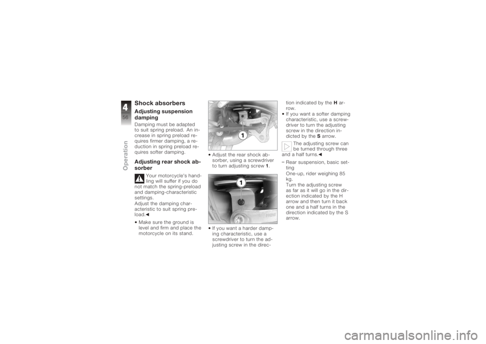
motorcycle on its stand. Adjust the rear shock ab-
sorber, using a screwdriver
to turn adjusting screw
1.
If you want a harder damp-
ing characteristic, use a
screwdriver to turn the ad-
justing screw in the direc- tion indicated by the
Har-
row.
If you want a softer damping
characteristic, use a screw-
driver to turn the adjusting
screw in the direction in-
dicted by the Sarrow.
The adjusting screw can
be turned through three
and a half turns.
Rear suspension, basic set-
ting
One-up, rider weighing 85
kg.
Turn the adjusting screw
as far as it will go in the dir-
ection indicated by the H
arrow and then turn it back
one and a half turns in the
direction indicated by the S
arrow.
456zOperation
Page 59 of 165
Electronic Suspension
Adjustment ESA
OE
SettingsElectronic Suspension Ad-
justment ESA provides a con-
venient way of adapting the
motorcycle to different condi-
tions. Three spring preload
settings can be combined
with three damping charac-
teristics to fine-tune the mo-
torcycle's suspension to the
load it carries and the surface
over which you want to ride.
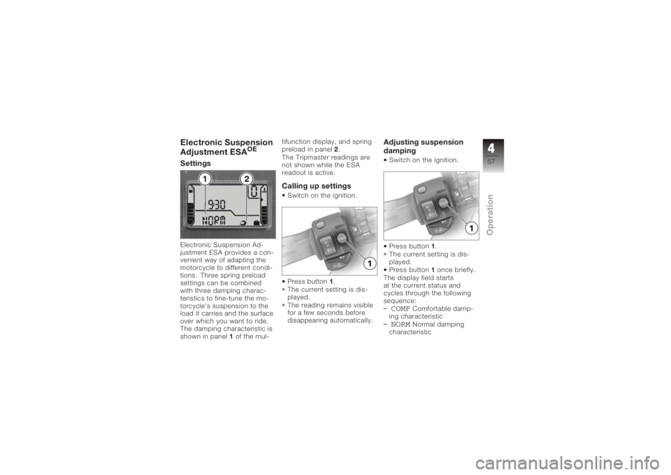
The damping characteristic is
shown in panel1of the mul- tifunction display, and spring
preload in panel
2.
The Tripmaster readings are
not shown while the ESA
readout is active.
Calling up settingsSwitch on the ignition.
Press button 1.
The current setting is dis-
played.
The reading remains visible
for a few seconds before
disappearing automatically.
Adjusting suspension
dampingSwitch on the ignition.
Press button 1.
The current setting is dis-
played.
Press button 1once briefly.
The display field starts
at the current status and
cycles through the following
sequence:COMF
Comfortable damp-
ing characteristic
NORM
Normal damping
characteristic
457zOperation
Page 106 of 165
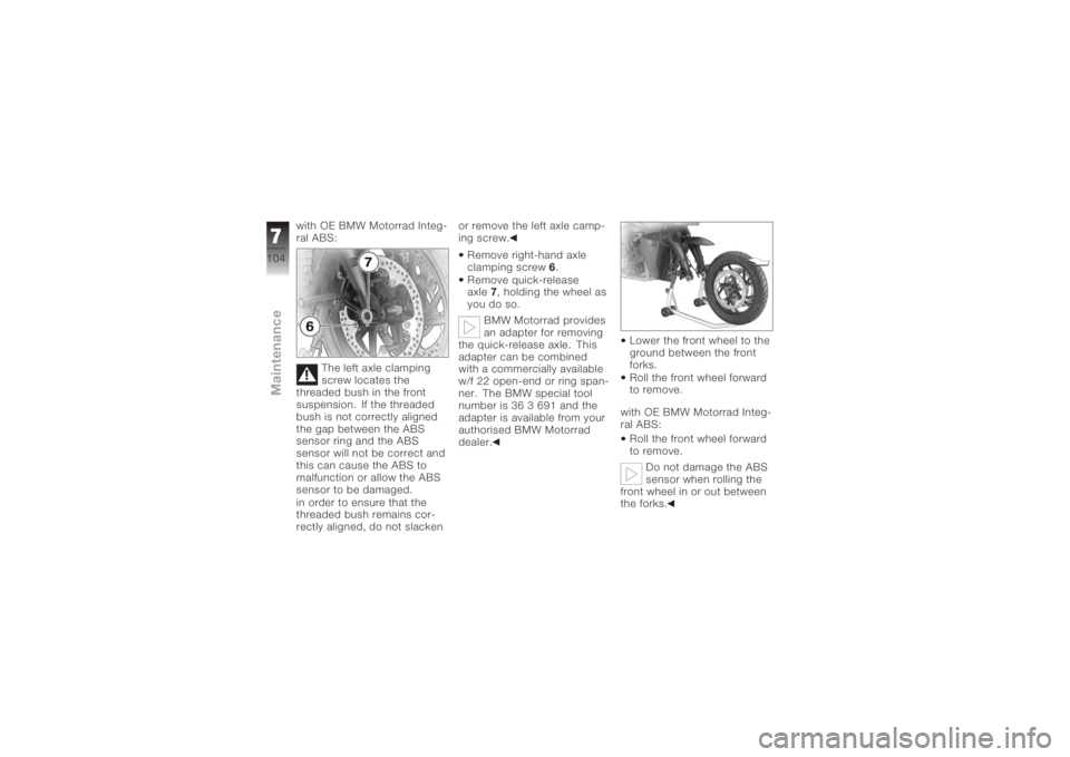
with OE BMW Motorrad Integ-
ral ABS:The left axle clamping
screw locates the
threaded bush in the front
suspension. If the threaded
bush is not correctly aligned
the gap between the ABS
sensor ring and the ABS
sensor will not be correct and
this can cause the ABS to
malfunction or allow the ABS
sensor to be damaged.
in order to ensure that the
threaded bush remains cor-
rectly aligned, do not slacken or remove the left axle camp-
ing screw.
Remove right-hand axle
clamping screw 6.
Remove quick-release
axle 7, holding the wheel as
you do so.
BMW Motorrad provides
an adapter for removing
the quick-release axle. This
adapter can be combined
with a commercially available
w/f 22 open-end or ring span-
ner. The BMW special tool
number is 36 3 691 and the
adapter is available from your
authorised BMW Motorrad
dealer. Lower the front wheel to the
ground between the front
forks.
Roll the front wheel forward
to remove.
with OE BMW Motorrad Integ-
ral ABS: Roll the front wheel forward
to remove.
Do not damage the ABS
sensor when rolling the
front wheel in or out between
the forks.
7104zMaintenance
Page 113 of 165
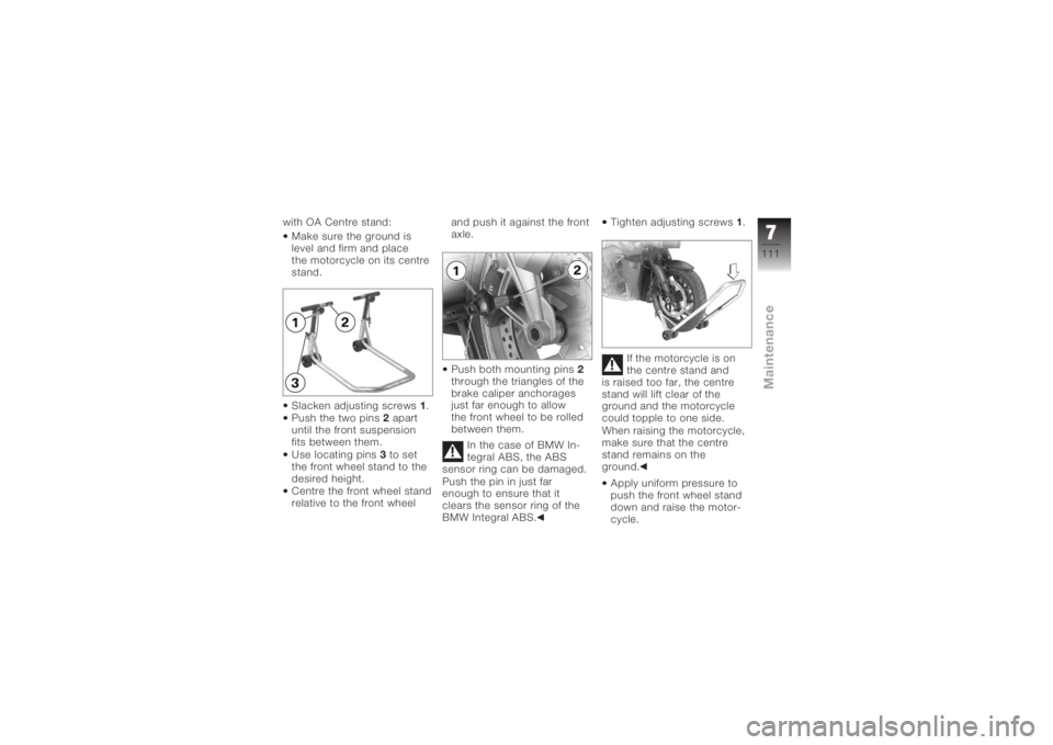
with OA Centre stand:Make sure the ground is
level and firm and place
the motorcycle on its centre
stand.
Slacken adjusting screws 1.
Push the two pins 2apart
until the front suspension
fits between them.
Use locating pins 3to set
the front wheel stand to the
desired height.
Centre the front wheel stand
relative to the front wheel and push it against the front
axle.
Push both mounting pins
2
through the triangles of the
brake caliper anchorages
just far enough to allow
the front wheel to be rolled
between them.
In the case of BMW In-
tegral ABS, the ABS
sensor ring can be damaged.
Push the pin in just far
enough to ensure that it
clears the sensor ring of the
BMW Integral ABS. Tighten adjusting screws
1.
If the motorcycle is on
the centre stand and
is raised too far, the centre
stand will lift clear of the
ground and the motorcycle
could topple to one side.
When raising the motorcycle,
make sure that the centre
stand remains on the
ground.
Apply uniform pressure to
push the front wheel stand
down and raise the motor-
cycle.
7111zMaintenance
Page 139 of 165
Final driveRear wheel drive, typeShaft drive with bevel gears
Final drive gear ratio 2.91 : 1Running gearFront suspension, typeDouble leading link
Front suspension, total suspension travel 115 mm, Static 125 mm, Dynamic
Rear suspension, type Single-tube gas-pressure shock absorber
Rear suspension, total suspension travel 135 mm, At wheel
9137zTechnical data