2008 BMW MOTORRAD K 1200 R heating
[x] Cancel search: heatingPage 4 of 165
Table of ContentsYou can also consult the in-
dex at the end of this Rider's
Manual if you want to find a
particular topic or item of in-
formation.
1 General instructions . . . 5
Overview . . . . . . . . . . . . . . . . . 6
Abbreviations and
symbols . . . . . . . . . . . . . . . . . . 6
Equipment . . . . . . . . . . . . . . . 7
Technical data . . . . . . . . . . . . 7
Currency . . . . . . . . . . . . . . . . . 7
2 General views . . . . . . . . . 9
General view, left side . . . 11
General view, right
side . . . . . . . . . . . . . . . . . . . . . 13
Underneath the seat . . . . . 15
Handlebar fitting, left . . . . . 16
Handlebar fitting, right . . . 17
Instrument cluster . . . . . . . 18
Headlight . . . . . . . . . . . . . . . 193 Status indicators . . . . . 21
Multifunction display . . . . . 22
Warning and telltale
lights . . . . . . . . . . . . . . . . . . . 22
ABS warning light
OE
..... 22
Function indicators . . . . . . 22
Warnings, general . . . . . . . 23
ABS warning
indicators . . . . . . . . . . . . . . . 30
4 Operation . . . . . . . . . . . . . 37
Ignition switch and
steering lock . . . . . . . . . . . . 38
Electronic immobiliser
(EWS) . . . . . . . . . . . . . . . . . . . 39
Hazard warning
flashers . . . . . . . . . . . . . . . . . 40
Tripmaster . . . . . . . . . . . . . . 41
On-board computerOE
... 43
Clock . . . . . . . . . . . . . . . . . . . 46
Emergency off switch (kill
switch) . . . . . . . . . . . . . . . . . . 47
Grip heating
OE
........... 47
Clutch . . . . . . . . . . . . . . . . . . 48
Brakes . . . . . . . . . . . . . . . . . . 48
Lights . . . . . . . . . . . . . . . . . . . 49 Headlight . . . . . . . . . . . . . . . 50
Turn indicators . . . . . . . . . . 50
Seat . . . . . . . . . . . . . . . . . . . . 51
Helmet holder . . . . . . . . . . . 53
Luggage loops . . . . . . . . . . 54
Mirrors . . . . . . . . . . . . . . . . . . 54
Spring preload . . . . . . . . . . 55
Shock absorbers . . . . . . . . 56
Electronic Suspension
Adjustment ESA
OE
....... 57
Tyres . . . . . . . . . . . . . . . . . . . 58
5 Riding . . . . . . . . . . . . . . . . 61
Safety instructions . . . . . . . 62
Checklist . . . . . . . . . . . . . . . . 64
Starting . . . . . . . . . . . . . . . . . 64
Pulling away with BMW
Integral ABS
OE
.......... 67
Running in . . . . . . . . . . . . . . 67
Parking your
motorcycle . . . . . . . . . . . . . . 71
Refuelling . . . . . . . . . . . . . . . 78
Brake system, general . . . 79
Brake system with BMW
Integral ABS
OE
.......... 79
Page 19 of 165
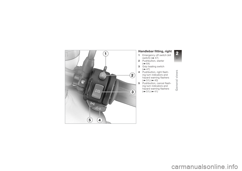
Handlebar fitting, right1Emergency off switch (kill
switch) ( 47)
2 Pushbutton, starter
( 64)
3 Grip heating switch
( 47)
4 Pushbutton, right flash-
ing turn indicators and
hazard warning flashers
( 51) ( 40)
5 Pushbutton, cancel flash-
ing turn indicators and
hazard warning flashers
( 51) ( 41)
217zGeneral views
Page 39 of 165
Operation
Ignition switch and steering
lock . .......................... 38
Electronic immobiliser (EWS) . . . 39
Hazard warning flashers . . . .... 40
Tripmaster .................... 41
On-board computer
OE
......... 43
Clock ......................... 46
Emergency off switch (kill
switch) ........................ 47
Grip heating
OE
................ 47
Clutch ........................ 48
Brakes ........................ 48
Lights ......................... 49
Headlight . .................... 50
Turn indicators . ............... 50
Seat . ......................... 51 Helmet holder . .
............... 53
Luggage loops . ............... 54
Mirrors . . . ..................... 54
Spring preload . ............... 55
Shock absorbers .............. 56
Electronic Suspension
Adjustment ESA
OE
............ 57
Tyres ......................... 58
437zOperation
Page 49 of 165
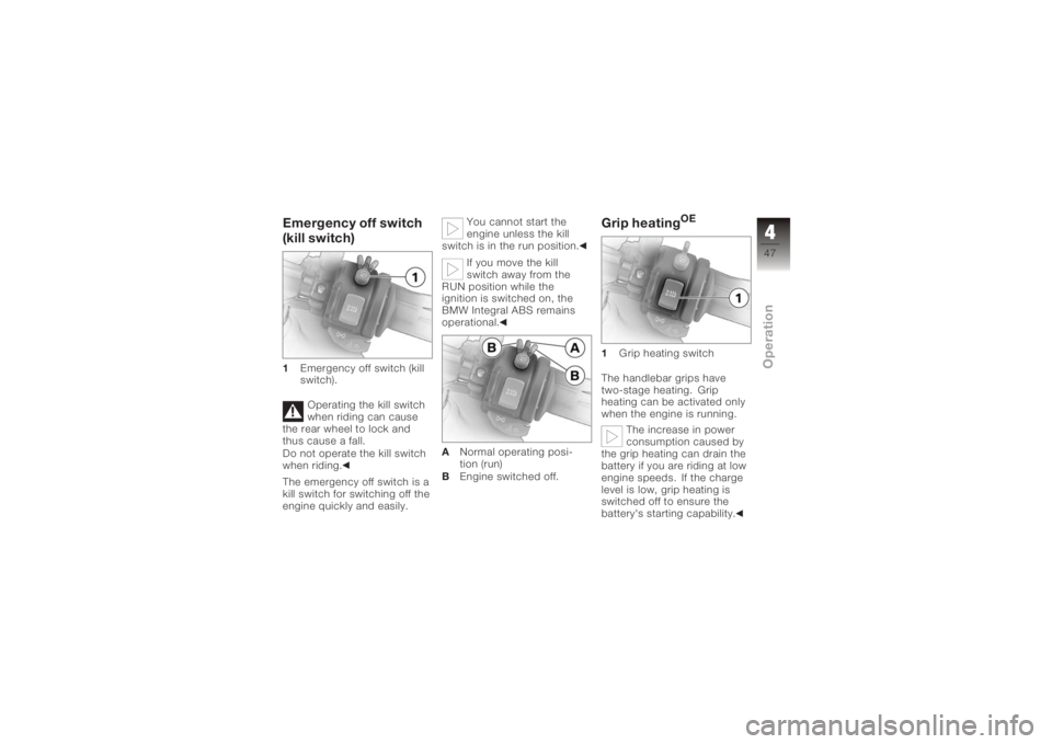
Emergency off switch
(kill switch)1Emergency off switch (kill
switch).
Operating the kill switch
when riding can cause
the rear wheel to lock and
thus cause a fall.
Do not operate the kill switch
when riding.
The emergency off switch is a
kill switch for switching off the
engine quickly and easily. You cannot start the
engine unless the kill
switch is in the run position.
If you move the kill
switch away from the
RUN position while the
ignition is switched on, the
BMW Integral ABS remains
operational.
A Normal operating posi-
tion (run)
B Engine switched off.
Grip heating
OE
1 Grip heating switch
The handlebar grips have
two-stage heating. Grip
heating can be activated only
when the engine is running. The increase in power
consumption caused by
the grip heating can drain the
battery if you are riding at low
engine speeds. If the charge
level is low, grip heating is
switched off to ensure the
battery's starting capability.
447zOperation
Page 50 of 165
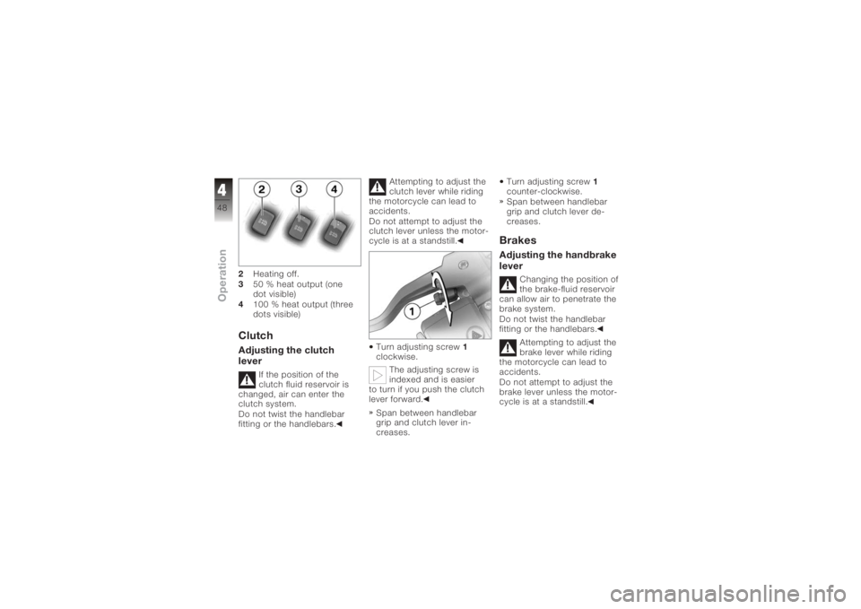
2Heating off.
3 50 % heat output (one
dot visible)
4 100 % heat output (three
dots visible)ClutchAdjusting the clutch
lever
If the position of the
clutch fluid reservoir is
changed, air can enter the
clutch system.
Do not twist the handlebar
fitting or the handlebars. Attempting to adjust the
clutch lever while riding
the motorcycle can lead to
accidents.
Do not attempt to adjust the
clutch lever unless the motor-
cycle is at a standstill.
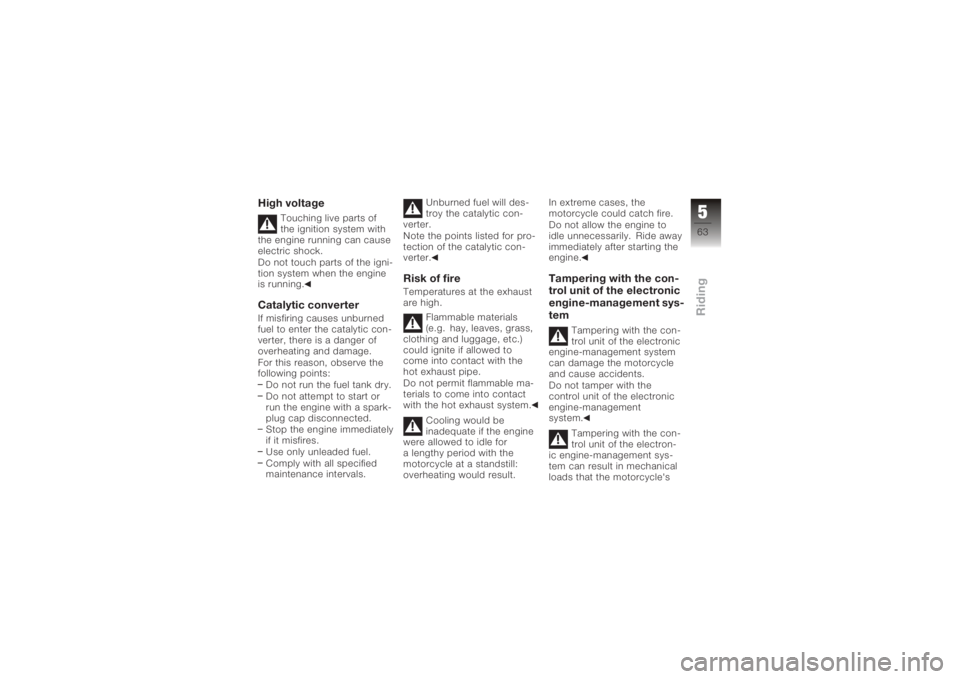
Turn adjusting screw 1
clockwise.
The adjusting screw is
indexed and is easier
to turn if you push the clutch
lever forward.
Span between handlebar
grip and clutch lever in-
creases. Turn adjusting screw
1
counter-clockwise.
Span between handlebar
grip and clutch lever de-
creases.
BrakesAdjusting the handbrake
lever
Changing the position of
the brake-fluid reservoir
can allow air to penetrate the
brake system.
Do not twist the handlebar
fitting or the handlebars.
Attempting to adjust the
brake lever while riding
the motorcycle can lead to
accidents.
Do not attempt to adjust the
brake lever unless the motor-
cycle is at a standstill.
448zOperation
Page 65 of 165
High voltage
Touching live parts of
the ignition system with
the engine running can cause
electric shock.
Do not touch parts of the igni-
tion system when the engine
is running.
Catalytic converterIf misfiring causes unburned
fuel to enter the catalytic con-
verter, there is a danger of
overheating and damage.
For this reason, observe the
following points:
Do not run the fuel tank dry.
Do not attempt to start or
run the engine with a spark-
plug cap disconnected.
Stop the engine immediately
if it misfires.
Use only unleaded fuel.
Comply with all specified
maintenance intervals. Unburned fuel will des-
troy the catalytic con-
verter.
Note the points listed for pro-
tection of the catalytic con-
verter.
Risk of fireTemperatures at the exhaust
are high.
Flammable materials
(e.g. hay, leaves, grass,
clothing and luggage, etc.)
could ignite if allowed to
come into contact with the
hot exhaust pipe.
Do not permit flammable ma-
terials to come into contact
with the hot exhaust system.
Cooling would be
inadequate if the engine
were allowed to idle for
a lengthy period with the
motorcycle at a standstill:
overheating would result. In extreme cases, the
motorcycle could catch fire.
Do not allow the engine to
idle unnecessarily. Ride away
immediately after starting the
engine.
Tampering with the con-
trol unit of the electronic
engine-management sys-
tem
Tampering with the con-
trol unit of the electronic
engine-management system
can damage the motorcycle
and cause accidents.
Do not tamper with the
control unit of the electronic
engine-management
system.
Tampering with the con-
trol unit of the electron-
ic engine-management sys-
tem can result in mechanical
loads that the motorcycle's
563zRiding
Page 116 of 165
Do not touch the glass
of new bulbs with your
fingers. Use a clean, dry cloth
to hold the bulbs when hand-
ling them. Dirt deposits, in
particular oil and grease, in-
terfere with heat radiation
from the bulb. This leads to
overheating and shortens the
bulb's operating life.
Low-beam and
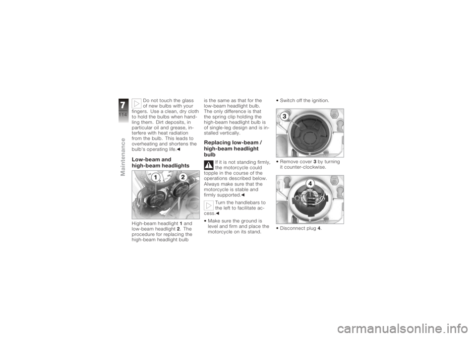
high-beam headlightsHigh-beam headlight 1and
low-beam headlight 2. The
procedure for replacing the
high-beam headlight bulb is the same as that for the
low-beam headlight bulb.
The only difference is that
the spring clip holding the
high-beam headlight bulb is
of single-leg design and is in-
stalled vertically.
Replacing low-beam /
high-beam headlight
bulb
If it is not standing firmly,
the motorcycle could
topple in the course of the
operations described below.
Always make sure that the
motorcycle is stable and
firmly supported.
Turn the handlebars to
the left to facilitate ac-
cess.
Make sure the ground is
level and firm and place the
motorcycle on its stand. Switch off the ignition.
Remove cover
3by turning
it counter-clockwise.
Disconnect plug 4.
7114zMaintenance
Page 129 of 165
Cleaning easily dam-
aged componentsPlasticsClean plastic parts with water
and BMW plastic care emul-
sion. This includes in particu-
lar:Windscreen
Headlight lens made of
plastic
Glass cover of the instru-
ment cluster
Black, unpainted parts
The use of unsuitable
products to clean plastic
parts can damage the sur-
face.
Do not use products that
contain alcohol or solvents to
clean plastic surfaces, and do
not use scouring agents.
Even fly-remover pads or
cleaning pads with hard surfaces can produce
scratches.
Soften stubborn dirt and
insects by covering the
affected areas with a wet
cloth.
WindscreenClean off dirt and insects with
a soft sponge and plenty of
water.
Fuel and chemical
solvents attack the
material of the windscreen;
the windscreen becomes
opaque or dull.
Do not use cleaning agents.ChromeUse plenty of water and BMW
shampoo to clean chrome,
particularly if it has been
exposed to road salt. Use
chrome polish for additional
treatment.
RadiatorClean the radiator regularly to
prevent overheating of the en-
gine due to inadequate cool-
ing.
For example, use a garden
hose with low water pressure.
Cooling fins can be bent
easily.
Take care not to bend the fins
when cleaning the radiator.RubberTreat rubber components with
water or BMW rubber-care
products.
Using silicone sprays for
the care of rubber seals
can cause damage.
Do not use silicone sprays
or other care products that
contain silicon.
8127zCare