Page 96 of 264

Technology for comfort, convenience and safety
94
Airbags
The following airbags are located under the
marked covers:
1Front airbags
2Coupe: Head airbags
3Side airbags
4Knee airbag
5Knee airbag
Protective action
To ensure that the safety systems con-
tinue to provide optimized protection,
please follow the adjustment instructions on
page47.<
The front airbags help protect the driver and
front passenger by responding to frontal
impacts in which safety belts alone cannot pro-
vide adequate restraint. When needed, the
head and side airbags help provide protection in
the event of a side impact. The relevant side air-
bag supports the side upper body area. The
head airbag supports the head. The knee airbag
protects the legs from colliding with the cockpit.
The airbags are deliberately not triggered in
every impact situation, e. g. less severe acci-
dents or rear-end collisions.
Do not apply adhesive materials to the
cover panels of the airbags, cover them or
modify them in any other way. Do not attempt to
remove the airbag restraint system from the
vehicle. Do not modify or tamper with either the
wiring or the individual components in the air-
bag system. This category includes the uphol-
stery in the center of the steering wheel, on the
instrument panel, the side trim panels on the
doors and on the Coupe, the roof pillars along with the sides of the headliner. Do not attempt
to remove or dismantle the steering wheel.
Do not touch the individual components
directly after the system has been triggered,
because there is a danger of burns.
In the event of malfunctions, deactivation, or
triggering of the airbag restraint system, have
the testing, repair, removal, and disposal of air-
bag generators carried out only by a BMW cen-
ter or a workshop that works according to BMW
repair procedures with appropriately trained
personnel and has the required explosives
licenses. Otherwise unprofessional attempts to
service the system could lead to failure in an
emergency or undesired airbag triggering,
either of which could result in personal injury.<
Warnings and information on the airbags is also
provided on the sun visors.
Automatic deactivation of front
passenger airbags
The occupation of the seat is detected by eval-
uating the impression on the occupied seat sur-
face of the front passenger seat. The system
correspondingly activates or deactivates the
front, knee and side airbags on the front pas-
senger side.
The current status of the front passenger
airbags, i.e. deactivated or activated, is
indicated by the indicator lamp over the interior
rearview mirror, refer to Operating state of front
passenger airbags below.<
Before transporting a child in the front
passenger seat, read the safety informa-
tion and follow the instructions under Trans-
porting children safely, refer to page56.
Page 98 of 264

Technology for comfort, convenience and safety
96
Convertible: rollover
protection system
The rollover protection system is automatically
activated in the event of an accident or a critical
driving situation, extreme inclination on the lon-
gitudinal axis, or loss of ground contact. The
rollover bars located behind the rear head
restraints are deployed within fractions of a sec-
ond.
As a supplement to the rollover bar integrated
into the windshield frame, the rollover protec-
tion system ensures that all vehicle occupants
have the necessary headroom.
Always keep the path of movement of the
rollover protection system clear.
In less severe accidents, you are protected by
the fastened safety belt and, depending on the
severity of the accident, the belt tensioner and
the multistage airbag restraint system.<
Lowering
If the rollover protection system experienced no
impact after automatic activation, then it can be
lowered again. No tools are necessary for this
purpose.
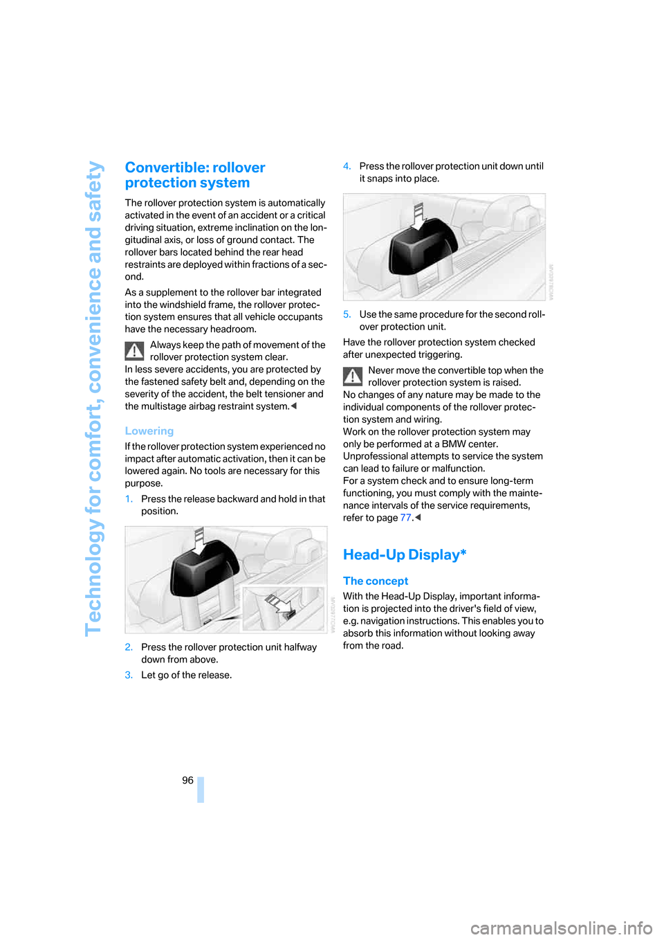
1.Press the release backward and hold in that
position.
2.Press the rollover protection unit halfway
down from above.
3.Let go of the release.4.Press the rollover protection unit down until
it snaps into place.
5.Use the same procedure for the second roll-
over protection unit.
Have the rollover protection system checked
after unexpected triggering.
Never move the convertible top when the
rollover protection system is raised.
No changes of any nature may be made to the
individual components of the rollover protec-
tion system and wiring.
Work on the rollover protection system may
only be performed at a BMW center.
Unprofessional attempts to service the system
can lead to failure or malfunction.
For a system check and to ensure long-term
functioning, you must comply with the mainte-
nance intervals of the service requirements,
refer to page77.<
Head-Up Display*
The concept
With the Head-Up Display, important informa-
tion is projected into the driver's field of view,
e.g. navigation instructions. This enables you to
absorb this information without looking away
from the road.
Page 228 of 264

Replacing components
226
Power failure
After a temporary power supply interruption,
some settings are lost. Take the following
steps:
>Seat, mirror and steering wheel memory
Store the positions again, refer to page49.
>Time and date
Reset, refer to text starting on page82.
>Radio
Store stations again, refer to page164.
>Navigation system
Wait until the system starts, refer to
page132.
Fuses
Never attempt to repair a blown fuse, and
do not replace a defective fuse with a sub-
stitute of another color or amperage rating, as
this could lead to overloading of the wiring, ulti-
mately resulting in a fire in the vehicle.<
Spare fuses and a pair of plastic tweezers are
located in the compartment for the onboard tool
kit, refer to page223.
Information on fuse allocation is located below
the bracket for the onboard tool kit, see below.
In glove compartment
1.Press the button on the back in the center of
partition1 and pull out the partition upward,
arrow2.
2.Press the coupling downward, arrow3, and
fold the lid 4 forward.
In luggage compartment
Fold the cover under the floor mat upward and
remove the bracket for the onboard tool kit.
Information on fuse allocation1 and additional
fuses2 are provided there.