2008 AUDI S5 clock
[x] Cancel search: clockPage 255 of 294
Downloaded from www.Manualslib.com manuals search engine Self-help253
Controls
Safety
Driving tips
General maintenance
Self-help
Technical data
– Now fit the crank handle onto the jack by inserting it
in the opening on the knob ⇒page 252, fig. 232. Turn the
crank handle clockwise or anti-clockwise to secure it in
place.
– Raise the vehicle by winding the crank handle until the
defective wheel is clear of the ground.Recesses at the front and rear of the door sills mark the jacking
points ⇒page 252, fig. 231. There is one jacking point for each
wheel. The distance from the jacking points to the wheel arches is
approximately 20 cm at the front and 40 cm at the rear. The jack may
only be applied at the seam of the jacking points shown.
An unstable surface under the jack may cause the vehicle to slip off
the jack. Always provide a firm base for the jack on the ground. If
necessary use a large, strong board or similar support. On a hard,
slippery surface (such as tiles) use a rubber mat or similar to prevent
the jack from slipping.
WARNING
•
Prevent the base of the jack from slipping – risk of injury.
•
The car can be damaged if the jack is not applied at the correct
jacking points. There is also a risk of injury since the jack can slip
off suddenly if it is not properly engaged.
Taking off the wheel and putting on the spare wheel
Step-by-step instructions for taking off the wheel and
putting on the spare wheel.Change the wheel as described below after loosening the
wheel bolts and raising the vehicle with the jack*.
Taking off the wheel
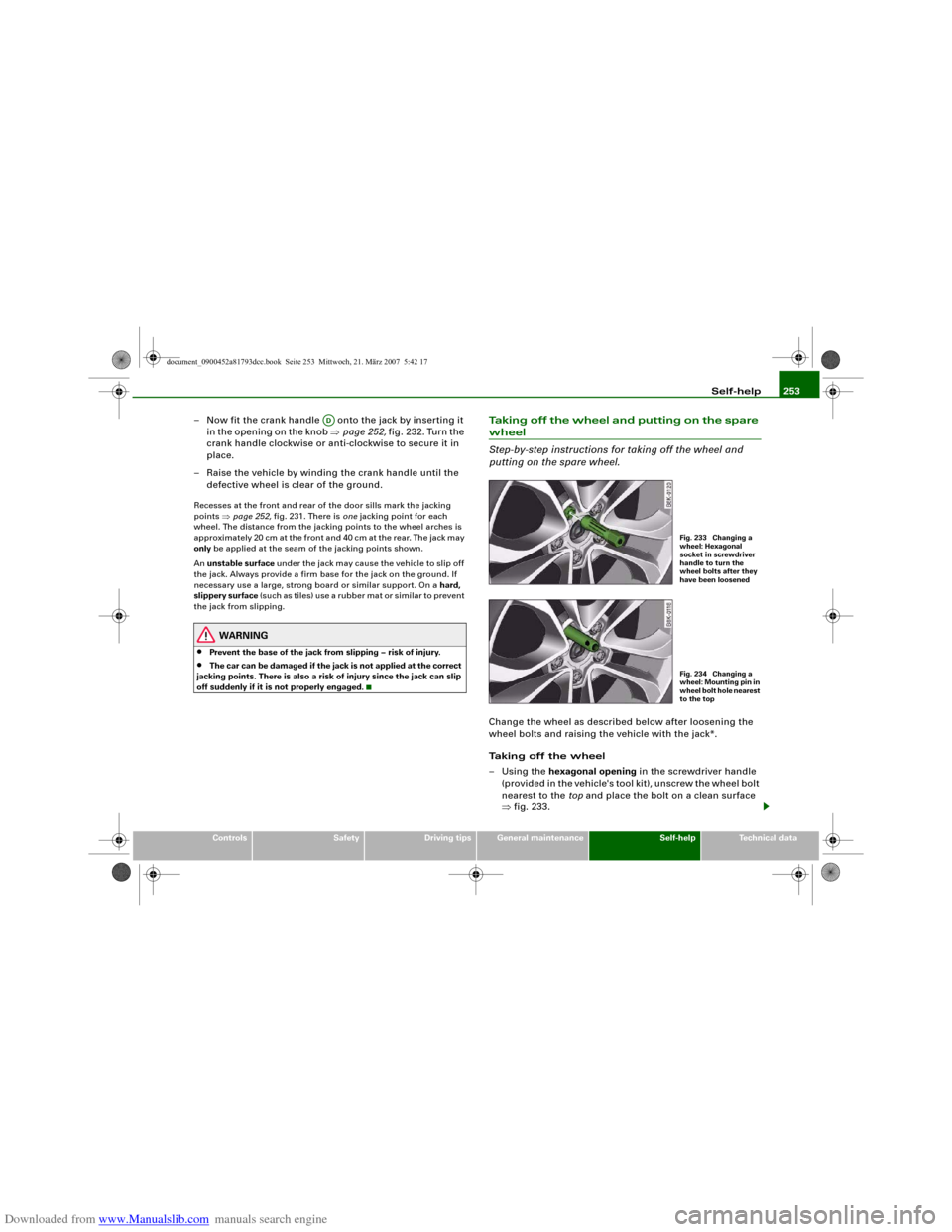
–Using the hexagonal opening in the screwdriver handle
(provided in the vehicle's tool kit), unscrew the wheel bolt
nearest to the top and place the bolt on a clean surface
⇒fig. 233.
AD
Fig. 233 Changing a
wheel: Hexagonal
socket in screwdriver
handle to turn the
wheel bolts after they
have been loosenedFig. 234 Changing a
wheel: Mounting pin in
wheel bolt hole nearest
to the top
document_0900452a81793dcc.book Seite 253 Mittwoch, 21. März 2007 5:42 17
Page 268 of 294
Downloaded from www.Manualslib.com manuals search engine Fuses and bulbs 266•
Incorrect handling of the high-voltage element of xenon gas-
discharge bulbs* can have potentially fatal consequences.
•
When changing bulbs, please take care not to injure yourself on
sharp edges, in particular on the headlight housing.Caution
•
Always remove the ignition key before carrying out any work on
the electrical system - danger of short circuiting!
•
Switch off the lights or parking lights before you change a bulb.
•
Take good care to avoid damaging any components.
•
Removing the lights in particular can lead to the paintwork
becoming damaged. This is another reason why we recommend
having the bulbs changed by a qualified workshop.For the sake of the environment
Please ask your specialist retailer how to dispose of used bulbs in
the proper manner.
Note
Place the parts you have removed on a soft cloth so that they do not
become scratched.•
Please check at regular intervals that all lighting (especially the
exterior lighting) on your vehicle is functioning properly. This is not
only in the interest of your own safety, but also in that of all other
road users.
•
Before changing a bulb, make sure you have the correct new
bulb.
•
Do not touch the glass part of the bulb with your bare hands, use
a cloth or paper towel instead. Otherwise, the fingerprints left on
the glass will vaporise as a result of the heat generated by the bulb,
be deposited on the reflector and impair its surface.
Bulbs with a bayonet fastenerBulbs with a bayonet fastener must be changed as follows:
Removing the bulb
– Lightly press the defective bulb into the bulb holder, then
turn it anti-clockwise and remove it.
– Do not touch the glass part of the new bulb with your
bare hands, use a cloth or paper towel instead.
Fitting the bulb
– Fit the new bulb, pressing it into the bulb holder, and turn
it clockwise as far as it will go.
– If necessary, use a cloth to remove any fingerprints from
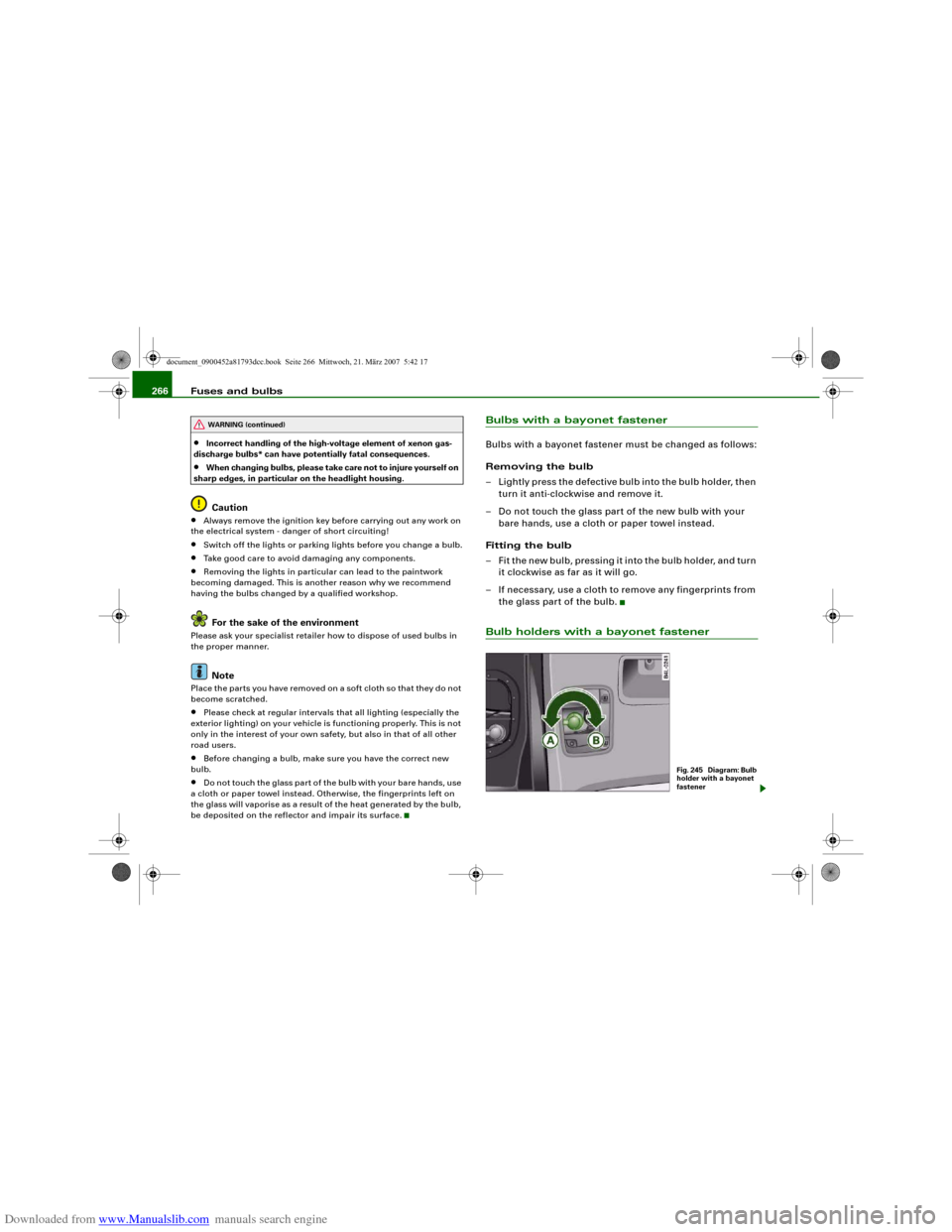
the glass part of the bulb.Bulb holders with a bayonet fastener
WARNING (continued)
Fig. 245 Diagram: Bulb
holder with a bayonet
fastener
document_0900452a81793dcc.book Seite 266 Mittwoch, 21. März 2007 5:42 17
Page 270 of 294
Downloaded from www.Manualslib.com manuals search engine Fuses and bulbs 268
Installing
– Perform all of the above steps in reverse sequence.The headlight must be inserted in two guides (on the underside of
the headlight). This is the only way to ensure that the headlight is
installed in the correct position. To determine whether the headlight
is correctly installed, check that it is aligned flush with adjacent
body parts (such as the wing panel).
Do not interchange the securing screws.
Caution
Please take particular care not to damage or scratch the adjacent
parts of the body when removing or installing the headlights.Applies to vehicles: with xenon headlight bulbsChanging bulb for turn signalsThe bulb is secured in the bulb carrier with a bayonet
fastener.
– Remove the headlight ⇒page 267.
– Take off the rubber cap (small cover) and remove the bulb
carrier.
– Lightly press the defective bulb into the bulb carrier, then
turn it anti-clockwise and remove it.
– Do not touch the glass part of the new bulb with your
bare hands, use a cloth or paper towel instead.
– Fit the new bulb, pressing it into the bulb carrier, and turn
it clockwise as far as it will go.
– If necessary, use a cloth to remove any fingerprints from
the glass part of the bulb.– Insert the bulb carrier into the headlight.
Note
Ensure that the rubber cap is seated correctly so that no water can
enter the unit.Changing bulb for front fog lightsPreparations
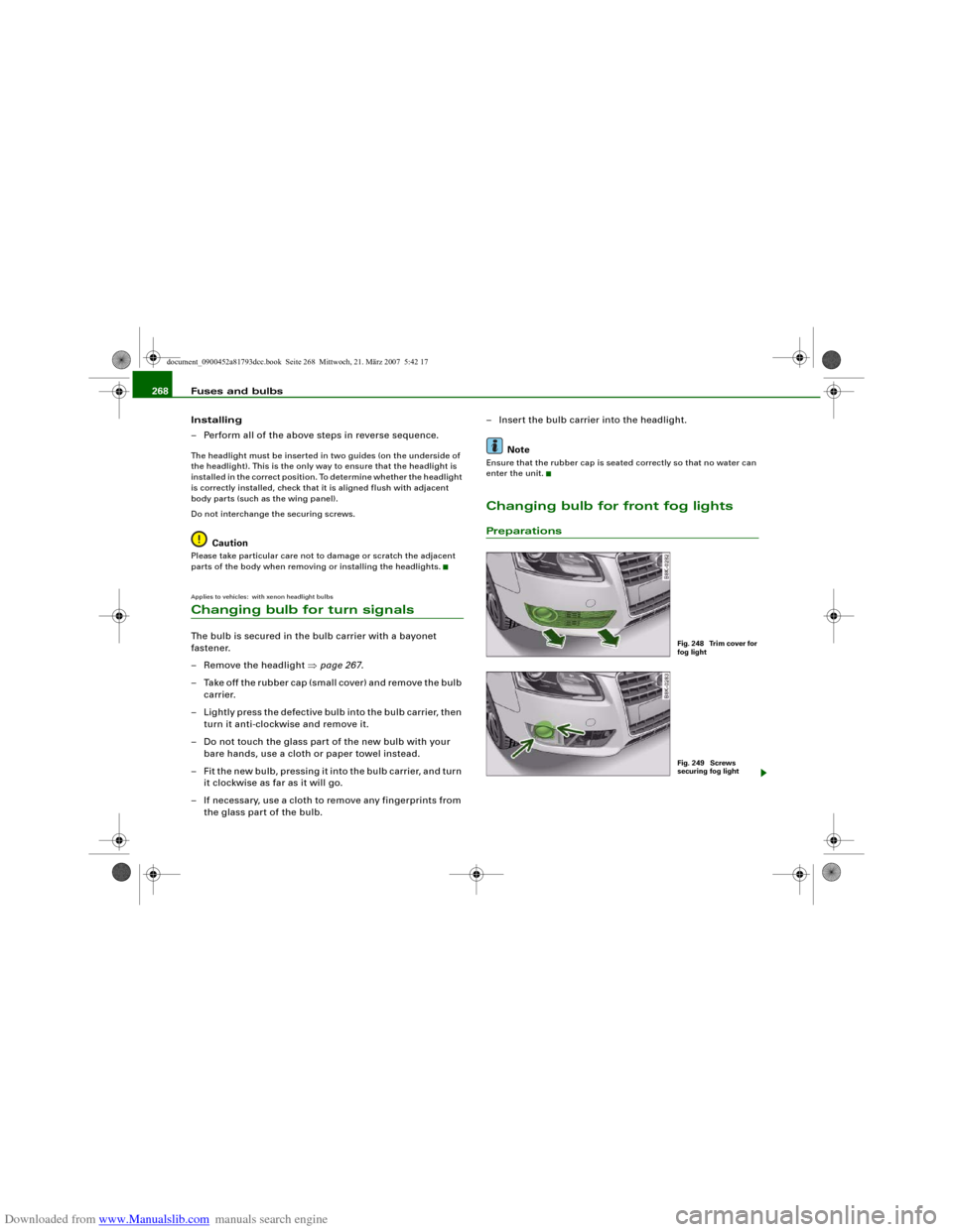
Fig. 248 Trim cover for
fog lightFig. 249 Screws
securing fog light
document_0900452a81793dcc.book Seite 268 Mittwoch, 21. März 2007 5:42 17
Page 271 of 294
Downloaded from www.Manualslib.com manuals search engine Fuses and bulbs269
Controls
Safety
Driving tips
General maintenance
Self-help
Technical data
The description for changing the bulb refers to the left fog
light; in principle the same procedure applies to the right
fog light.
– Switch off the ignition and the lights.
– Detach the trim cover ⇒page 268, fig. 248 (pull it care-
fully in the direction of the arrow).
– Remove the two securing screws ⇒page 268, fig. 249
and pull the fog light unit out of the bumper.
– Unplug the electrical connector.
CautionThe trim cover is secured to the bumper by several retaining hooks.
Do not use force when removing the trim cover to avoid damaging
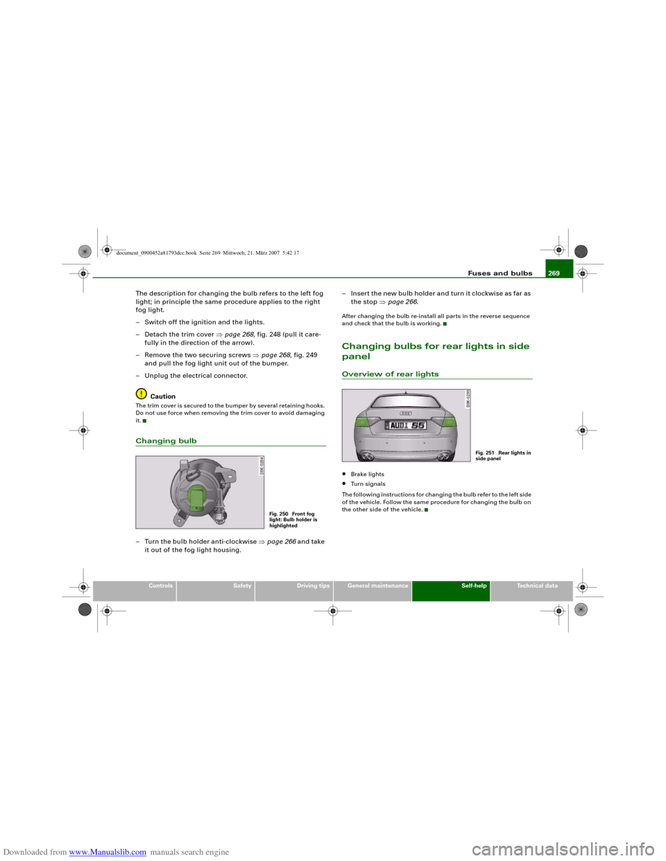
it.Changing bulb– Turn the bulb holder anti-clockwise ⇒page 266 and take
it out of the fog light housing.– Insert the new bulb holder and turn it clockwise as far as
the stop ⇒page 266.
After changing the bulb re-install all parts in the reverse sequence
and check that the bulb is working.Changing bulbs for rear lights in side
panelOverview of rear lights•
Brake lights
•
Turn signals
The following instructions for changing the bulb refer to the left side
of the vehicle. Follow the same procedure for changing the bulb on
the other side of the vehicle.
Fig. 250 Front fog
light: Bulb holder is
highlighted
Fig. 251 Rear lights in
side panel
document_0900452a81793dcc.book Seite 269 Mittwoch, 21. März 2007 5:42 17
Page 272 of 294
Downloaded from www.Manualslib.com manuals search engine Fuses and bulbs 270Removing rear light
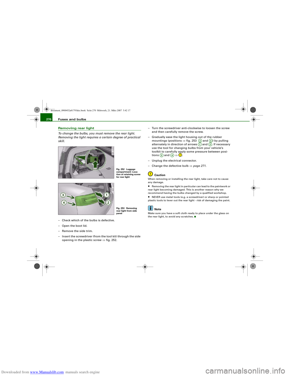
To change the bulbs, you must remove the rear light.
Removing the light requires a certain degree of practical
skill.– Check which of the bulbs is defective.
–Open the boot lid.
– Remove the side trim.
– Insert the screwdriver (from the tool kit) through the side
opening in the plastic screw ⇒fig. 252.– Turn the screwdriver anti-clockwise to loosen the screw
and then carefully remove the screw.
– Gradually ease the light housing out of the rubber
mountings (positions ⇒fig. 253 and ) by pulling
alternately in direction of arrows and . If necessary
use the tool for changing bulbs from your vehicle's
toolkit to carefully apply some pressure between posi-
tions and ⇒.
– Unplug the electrical connector.
– Change the defective bulb ⇒page 271.
Caution
When removing or installing the rear light, take care not to cause
any damage.•
Removing the rear light in particular can lead to the paintwork or
rear light becoming damaged. This is another reason why we
recommend having the bulbs changed by a qualified workshop.
•
NEVER use metal tools (e.g. a screwdriver) or sharp or pointed
plastic tools to lever out the rear light - risk of damaging the paint.Note
Make sure you have a soft cloth ready to place under the glass on
the rear light, to avoid any scratches.
Fig. 252 Luggage
compartment: Loca-
tion of retaining screw
for rear lightFig. 253 Removing
rear light from side
panel
A3
A4
A1
A2
A3
A4
document_0900452a81793dcc.book Seite 270 Mittwoch, 21. März 2007 5:42 17
Page 274 of 294
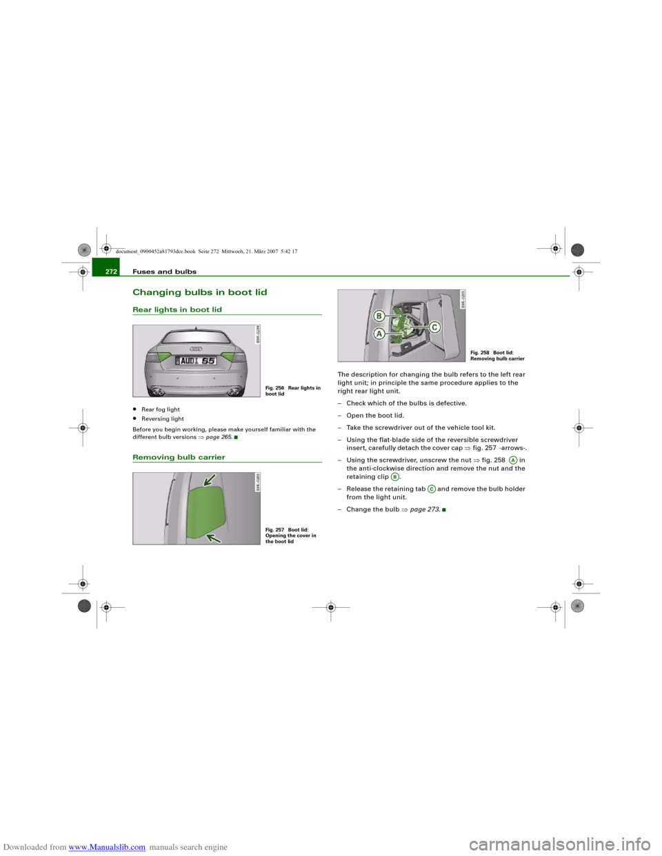
Downloaded from www.Manualslib.com manuals search engine Fuses and bulbs 272Changing bulbs in boot lidRear lights in boot lid•
Rear fog light
•
Reversing light
Before you begin working, please make yourself familiar with the
different bulb versions ⇒page 265.
Removing bulb carrier
The description for changing the bulb refers to the left rear
light unit; in principle the same procedure applies to the
right rear light unit.
– Check which of the bulbs is defective.
– Open the boot lid.
– Take the screwdriver out of the vehicle tool kit.
– Using the flat-blade side of the reversible screwdriver
insert, carefully detach the cover cap ⇒fig. 257 -arrows-.
– Using the screwdriver, unscrew the nut ⇒fig. 258 in
the anti-clockwise direction and remove the nut and the
retaining clip .
– Release the retaining tab and remove the bulb holder
from the light unit.
– Change the bulb ⇒page 273.
Fig. 256 Rear lights in
boot lidFig. 257 Boot lid:
Opening the cover in
the boot lid
Fig. 258 Boot lid:
Removing bulb carrier
AA
AB
AC
document_0900452a81793dcc.book Seite 272 Mittwoch, 21. März 2007 5:42 17
Page 275 of 294
Downloaded from www.Manualslib.com manuals search engine Fuses and bulbs273
Controls
Safety
Driving tips
General maintenance
Self-help
Technical data
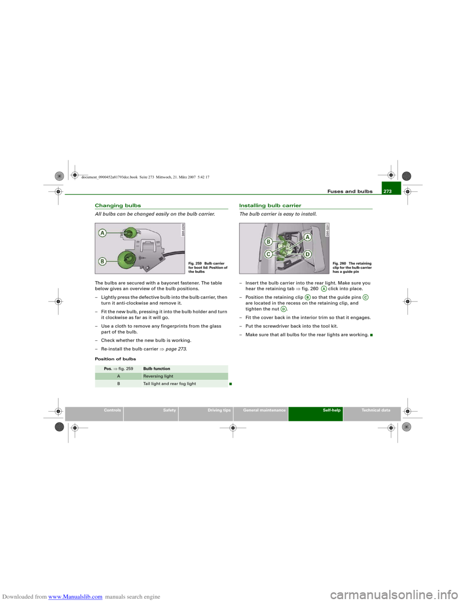
Changing bulbs
All bulbs can be changed easily on the bulb carrier.The bulbs are secured with a bayonet fastener. The table
below gives an overview of the bulb positions.
– Lightly press the defective bulb into the bulb carrier, then
turn it anti-clockwise and remove it.
– Fit the new bulb, pressing it into the bulb holder and turn
it clockwise as far as it will go.
– Use a cloth to remove any fingerprints from the glass
part of the bulb.
– Check whether the new bulb is working.
– Re-install the bulb carrier ⇒page 273.Position of bulbs
Installing bulb carrier
The bulb carrier is easy to install.– Insert the bulb carrier into the rear light. Make sure you
hear the retaining tab ⇒fig. 260 click into place.
– Position the retaining clip so that the guide pins
are located in the recess on the retaining clip, and
tighten the nut .
– Fit the cover back in the interior trim so that it engages.
– Put the screwdriver back into the tool kit.
– Make sure that all bulbs for the rear lights are working.
Pos. ⇒fig. 259
Bulb function
A
Reversing light
B
Tail light and rear fog light
Fig. 259 Bulb carrier
for boot lid: Position of
the bulbs
Fig. 260 The retaining
clip for the bulb carrier
has a guide pin
AA
AB
AC
AD
document_0900452a81793dcc.book Seite 273 Mittwoch, 21. März 2007 5:42 17
Page 287 of 294
Downloaded from www.Manualslib.com manuals search engine Index285
Controls
Safety
Driving tips
General maintenance
Self-help
Technical data Blower
Deluxe automatic air conditioner . . . . 94
Deluxe automatic air conditioner plus . .
102
Bonnet
Closing . . . . . . . . . . . . . . . . . . . . . . . . . 221
Opening . . . . . . . . . . . . . . . . . . . . . . . . 220
Releasing . . . . . . . . . . . . . . . . . . . . . . . 220
Boot
SeeLoading luggage compartment . 158
SeeLuggage compartment . . . . . . . . . 75
Boot lid
Central locking system . . . . . . . . . . . . . 48
Manual release . . . . . . . . . . . . . . . . . . . . 49
Brake system
Brake assist system . . . . . . . . . . . . . . . 187
Brake fluid . . . . . . . . . . . . . . . . . . . . . . 227
Brake light defective . . . . . . . . . . . . . . . 36
Brake pads worn . . . . . . . . . . . . . . . . . . 36
Brake servo . . . . . . . . . . . . . . . . . . . . . . 189
Electro-mechanical parking brake . . . 119
General notes . . . . . . . . . . . . . . . . . . . . 189
Malfunction . . . . . . . . . . . . . . . . . . . . . . 31
Warning lamp . . . . . . . . . . . . . . . . . . . . 19
Bulb holder
Bayonet fastener . . . . . . . . . . . . . . . . . 266
Bulb monitor . . . . . . . . . . . . . . . . . . . . . . . . 36
Bulbs
Bayonet fastener . . . . . . . . . . . . . . . . . 266
Changing (general notes) . . . . . . . . . . 265
Bulbs, changing . . . . . . . . . . . . . . . . . . . . 265
Brake lights . . . . . . . . . . . . . . . . . . . . . 269
Bulb holder with bayonet fastener . . 266Front fog lights . . . . . . . . . . . . . . . . . . 268
Number plate light . . . . . . . . . . . . . . . 274
Rear fog light . . . . . . . . . . . . . . . . . . . . 272
Rear lights . . . . . . . . . . . . . . . . . . . . . . 269
Reversing light . . . . . . . . . . . . . . . . . . . 272
Turn signals (rear) . . . . . . . . . . . . . . . . 269
Business equipment . . . . . . . . . . . . . . . . . 240
CCapacities . . . . . . . . . . . . . . . . . . . . . . . . . . 279
Car keys . . . . . . . . . . . . . . . . . . . . . . . . . . . . 38
Care of vehicle . . . . . . . . . . . . . . . . . . . . . . 210
Catalytic converter . . . . . . . . . . . . . . . . . . 195
Central locking system . . . . . . . . . . . . . . . . 42
Boot lid . . . . . . . . . . . . . . . . . . . . . . . . . . 48
Deadlock mechanism . . . . . . . . . . . . . . 45
Fuel tank flap . . . . . . . . . . . . . . . . . . . . 217
Locking . . . . . . . . . . . . . . . . . . . . . . . . . . 45
Locking and unlocking the vehicle from
inside . . . . . . . . . . . . . . . . . . . . . . . . . . 46
Manual locking . . . . . . . . . . . . . . . . . . . . 47
Opening and closing windows . . . . . . . 50
Switches on driver's door . . . . . . . . . . . 46
Unlocking . . . . . . . . . . . . . . . . . . . . . . . . 45
Changing a wheel . . . . . . . . . . . . . . . . . . . 250
Changing bulbs
SeeBulbs . . . . . . . . . . . . . . . . . . . . . . . 265
Chassis number . . . . . . . . . . . . . . . . . . . . . 279
Child safety . . . . . . . . . . . . . . . . . . . . . . . . 175
Child safety seat . . . . . . . . . . . . . . . . . . . . 176
Child seat categories . . . . . . . . . . . . . . 176
Fitting . . . . . . . . . . . . . . . . . . . . . . . . . . 179ISOFIX system . . . . . . . . . . . . . . . . . . . . 181
On front passenger's seat . . . . . . . . . . 176
Safety notes . . . . . . . . . . . . . . . . . . . . . 175
Cigarette lighter . . . . . . . . . . . . . . . . . . . . . . 85
Cleaning . . . . . . . . . . . . . . . . . . . . . . . . . . . 210
Cleaning Alcantara . . . . . . . . . . . . . . . . . . 216
Cleaning seat covers
Alcantara . . . . . . . . . . . . . . . . . . . . . . . . 216
Natural leather . . . . . . . . . . . . . . . . . . . 215
Textile covers . . . . . . . . . . . . . . . . . . . . 213
Cleaning textile covers and trim parts . . 213
Clock, setting . . . . . . . . . . . . . . . . . . . . . . . . 13
Closing
Bonnet . . . . . . . . . . . . . . . . . . . . . . . . . . 221
Coat hooks . . . . . . . . . . . . . . . . . . . . . . . . . . 90
Colour code . . . . . . . . . . . . . . . . . . . . . . . . 279
Compact temporary spare wheel
SeeSpare wheel . . . . . . . . . . . . . . . . . . 246
Compartment for (sun)glasses . . . . . . . . . 89
Compass in mirror . . . . . . . . . . . . . . . . . . . . 68
Controls and displays
Overview . . . . . . . . . . . . . . . . . . . . . . . . . . 9
Convenience close function . . . . . . . . . . . . 50
Convenience open function . . . . . . . . . . . . 50
Cooling system
Anti-freeze additive . . . . . . . . . . . . . . . 224
Checking coolant level . . . . . . . . . . . . 225
Coolant . . . . . . . . . . . . . . . . . . . . . . . . . 224
Coolant temperature gauge . . . . . . . . . 11
Malfunction . . . . . . . . . . . . . . . . . . . . . . 32
Radiator fan . . . . . . . . . . . . . . . . . . . . . 226
Topping up coolant . . . . . . . . . . . . . . . 226
document_0900452a81793dcc.book Seite 285 Mittwoch, 21. März 2007 5:42 17