2008 AUDI S4 boot
[x] Cancel search: bootPage 195 of 342

Safe driving193
Controls
Safety
Driving tips
General maintenance
Self-help
Technical data
inside. In this case the child wo
uld be unable to get out of the
vehicle without help. This could have fatal consequences.
•
Never allow children to play in or around the vehicle. Always
close and lock the boot lid and all the doors when you leave the
vehicle.
•
Never let passengers ride in the luggage compartment. All
occupants must be properly restrained by the seat belts at all
times ⇒page 194 .Note
•
Air circulation in the vehicle helps reduce fogging of the
windows. Used air escapes through ventilation slots in the rear of
the vehicle. Make sure that these ventilation slots are not
obstructed.
•
Suitable belts for securing loads to the fastening rings* are
commercially available.
Applies to vehicles: with fastening ringsFastening rings
Unsecured loads are a hazard to all vehicle occupants.There are fastening rings in the luggage compartment
which can be used to secure luggage and other objects
⇒ page 79 .
– Use the fastening rings to secure items safely in the luggage compartment ⇒ in “Loading the luggage
compartment” on page 79.During a collision or an accident, even small and light objects can
possess so much energy that they can cause very severe injuries.
The amount of this “kinetic energy” depends on the speed of the vehicle and the weight of the object. The most significant factor,
however, is the speed of the vehicle.
An example: An object weighing 4.5 kg is lying unsecured in the
vehicle. During a frontal collision at a speed of 50 km/h, this object
generates a force corresponding to 20 times its weight. That means
that the effective weight of the object increases to about 90 kg. You
can imagine the severity of the injuries which might be sustained if
this “projectile” strikes an occupant as it flies through the
passenger compartment.
WARNING
If items of luggage or other obje
cts are secured to the fastening
rings with inappropriate or da maged retaining cords, injuries
could result in the event of sudden braking or a collision.•
To prevent pieces of luggage or other objects from flying
forward, always use appropriate retaining cords which are prop-
erly secured to the fastening rings.
•
Never secure a child seat on the fastening rings.
WARNING (continued)
document_0900452a81b1b9de.book Seite 193 Donnerstag, 26. Juli 2007 9:16 09
--4 -
-T
[I]
-+
•
•
+-
Page 284 of 342

Self-help
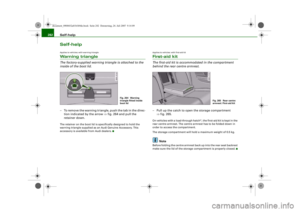
282Self-helpApplies to vehicles: with warning triangleWarning triangleThe factory-supplied warning tr iangle is attached to the
inside of the boot lid.– To remove the warning triangle, push the tab in the direc-
tion indicated by the arrow ⇒fig. 264 and pull the
retainer down.The retainer on the boot lid is specifically designed to hold the
warning triangle supplied as an Audi Genuine Accessory. This
accessory is available from Audi dealers.
Applies to vehicles: with first-aid kitFirst-aid kitThe first-aid kit is accommodated in the compartment
behind the rear centre armrest.– Pull up the catch to open the storage compartment ⇒fig. 265.On vehicles with a load-through hatc h*, the first-aid kit is kept in the
rear centre armrest. The centre armrest has to be folded down in
order to access the compartment.
The storage compartment will hold a maximum weight of 0.5 kg.
Note
Before folding the centre armrest back up into the rear seat backrest
make sure the lid of the storag e compartment is properly closed.
Fig. 264 Warning
triangle fitted inside
boot lid
Fig. 265 Rear centre
armrest: First-aid kit
document_0900452a81b1b9de.book Seite 282 Donnerstag, 26. Juli 2007 9:16 09
--4 -
-T
-+ +-
•
[I]
•
Page 286 of 342

Self-help
284If you need the tools, the Tyre Mobili ty System or the jack*, you will
have to open the floor panel and take out the spare wheel*
⇒ page 284 .
The tool kit includes:•
A hook for removing hub caps
•
Pin for mounting a wheel
•
Screwdriver with reversible blade
•
Tool for changing bulbs
•
Interchangeable socket (Torx socket for changing bulbs)
•
Crank handle for jack
•
Adapter for anti-theft wheel bolts*
•
Jack*
•
Box spanner for wheel bolts
•
Towline anchorage
Some of the parts listed are only fitted on certain models or are
optional extras.
Before stowing the jack* again, wind down the arm of the jack as far
as it will go.
WARNING
•
Do not use the hexagonal socket in the screwdriver handle to
tighten the wheel bolts. It is not po ssible to tighten the bolts with
the required torque – risk of accident.
•
The jack supplied by the factor y is only designed for changing
wheels on this model. On no account attempt to use it for lifting
heavier vehicles or other loads – risk of injury.
•
Never start the engine when the vehicle is on the jack - risk of
accident.
•
If work has to be done under the ve h i cl e , e n su re t h a t i t is sa fe l y
supported on stands designed for th e purpose, otherwise there is
a risk of injury.
Applies to vehicles: with compact temporary spare wheelCompact temporary spare wheel*The spare wheel is carried in the wheel well under the
floor panel in the luggage compartment. It is only
intended for temporary use over short distances.Taking out the spare wheel
– Lift the floor panel by the plastic handle ⇒fig. 268.
– Hook the handle onto the luggage compartment weath- erstrip.
– Turn the centre plastic knob ⇒ fig. 268 anti-clockwise.
– Take out the spare wheel.
– Unhook the floor panel before closing the boot lid.
Securing the defective wheel in the spare wheel
well
– Place the wheel in the spare wheel well and secure it with the plastic knob.
– Unhook the floor panel before closing the boot lid.
Fig. 268 Spare wheel
document_0900452a81b1b9de.book Seite 284 Donnerstag, 26. Juli 2007 9:16 09
--4 -
-T
-+ +-
•
Page 302 of 342

Fuses and bulbs
300Fuses and bulbsFusesChanging a fuse
If a fuse has blown it must be replaced.– Identify the fuse for the failed component.
– Switch off the ignition and the component concerned.
– Remove the fuse box cover ⇒fig. 283.
– Take the plastic clip from inside the fuse cover, fit it onto
the blown fuse, and pull the fuse out.
– Replace the blown fuse (which will have a melted metal strip) with a new fuse of the same amp rating.The various electrical circuits are protected by fuses. The fuse boxes
are located behind covers on the left and right sides of the dash
panel and in the compartment on the right side of the boot.
A plastic clip for removing the fuses is provided in the fuse cover on
the left side of the dash panel. There is also a sticker listing the fuses
in each of the fuse boxes in the dash panel.
Caution
Never attempt to “repair” a fuse or replace it by fitting a fuse with a
higher rating - risk of fire! It could also cause damage to other parts
of the electrical system.
Note
If a newly replaced fuse blows again after a short time, the electrical
system must be checked by a qualified workshop as soon as
possible.Fuses on the driver's sideSome of the items listed are only fitted on certain models or are
optional extras.
Please note that the following list, while correct at the time of
printing, is subject to alterations. If discrepancies should occur,
please refer to the sticker on the inside of the fuse cover for the
correct information for your vehicle.
Fig. 283 Left side of
dash panel: Fuse cover
Fig. 284 Diagram of
fuse box (left-hand
drive vehicle)
document_0900452a81b1b9de.book Seite 300 Donnerstag, 26. Juli 2007 9:16 09
--4 -
-T
CD
•
-+ +-
Page 306 of 342

Fuses and bulbs
304BulbsChanging bulbs
Changing bulbs requires a certain degree of practical
skill.You can change the following bulbs for exterior lights yourself:•
Halogen headlights: Bulb for dipped headlights
•
Halogen headlights: Bulb for main beam headlights
•
Bulb for fog light
•
Bulbs for rear lights in boot lid
•
Bulbs for rear lights in side panel
•
Bulbs for number plate light
The following bulbs should only be changed by a qualified work-
shop :
•
Halogen headlights: Bulb for turn signals
•
Halogen headlights: Bulb for side lights
•
Xenon headlights*: Bulb for turn signals
•
Xenon headlights*: Light source for daytime running
lights/parki ng lights
•
Bulb for headlights: Bi-xenon lights ⇒
•
Light source for turn signal in exterior mirror housing
•
Light source for high-level brake light
As a rule, you require a certain degree of practical skill to change
defective bulbs. This applies in particular to those bulbs which are
only accessible from the engine compartment.
If in doubt, we recommend that you have defective bulbs changed
by a qualified workshop or qualified mechanic.
If you do decide to change bulbs in the engine compartment your-
self, be aware of the safety risks involved ⇒page 255 ⇒ .
Types of bulbs
You must only replace a bulb with a bulb of the same type. Informa-
tion regarding e.g. the wattage can be found on the base of the
bulb.
4
Cigarette lighter
15
5
Parking aid
5
6
Phone pre-installation without handsfree sys-
tem (VDA interface)
5
7
Control unit for adap tive cruise control
15
8
Vacant
9
EPB switch (electro-mechanical parking brake)
5
10
Lane change assist feature
5
11
Seat heating, rear
5
12
Airbag
5
No.
Electrical equipment
amps
Front bulb (12 V)
Vers io n
Dipped-beam headlights (halogen)
55 W (H7)
Main beam headlights (halogen)
55 W (H7)
Front fog lights
55 W (H7)
Rear bulb (12 V)
Vers io n
Brake lights / tail lights
P 21 W
Turn signals (rear)
P 21 W
Reversing lights
W 16 W
Rear fog light
H 21 W
Number plate lights
5 W
document_0900452a81b1b9de.book Seite 304 Donnerstag, 26. Juli 2007 9:16 09
--4 -
1111
-
T
1111
-
6
1111
-
1111
-
1111
-
•
6
-+ +-
Page 314 of 342

Fuses and bulbs
312Applies to vehicles: with halogen main beam headlightsRemoving rear light
To change the bulbs, you must remove the rear light.
Removing the light requires a certain degree of practical
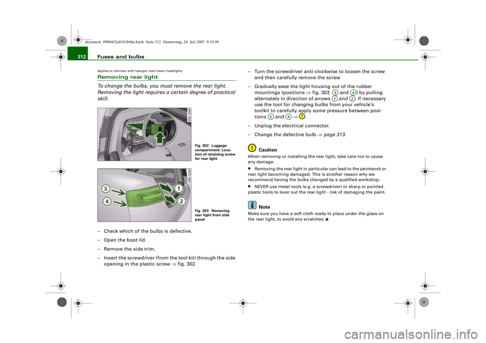
skill.– Check which of the bulbs is defective.
–Open the boot lid.
– Remove the side trim.
– Insert the screwdriver (from the tool kit) through the side
opening in the plastic screw ⇒fig. 302. – Turn the screwdriver anti-clockwise to loosen the screw
and then carefully remove the screw.
– Gradually ease the light housing out of the rubber mountings (positions ⇒fig. 303 and ) by pulling
alternately in direction of arrows and . If necessary
use the tool for changing bulbs from your vehicle's
toolkit to carefully apply some pressure between posi-
tions and ⇒.
– Unplug the electrical connector.
– Change the defective bulb ⇒page 313.
Caution
When removing or installing the rear light, take care not to cause
any damage.•
Removing the rear light in particular can lead to the paintwork or
rear light becoming damaged. Th is is another reason why we
recommend having the bulbs changed by a qualified workshop.
•
NEVER use metal tools (e.g. a screwdriver) or sharp or pointed
plastic tools to lever out the rear light - risk of damaging the paint.Note
Make sure you have a soft cloth ready to place under the glass on
the rear light, to avoid any scratches.
Fig. 302 Luggage
compartment: Loca-
tion of retaining screw
for rear lightFig. 303 Removing
rear light from side
panel
A3
A4
A1
A2
A3
A4
document_0900452a81b1b9de.book Seite 312 Donnerstag, 26. Juli 2007 9:16 09
--4 -
-T
0
CD
-+ +-
•
Page 316 of 342

Fuses and bulbs
314Changing bulbs in boot lidRear lights in boot lid•
Rear fog light
•
Reversing light
Before you begin working, please make yourself familiar with the
different bulb versions ⇒ page 304.
Removing bulb carrier
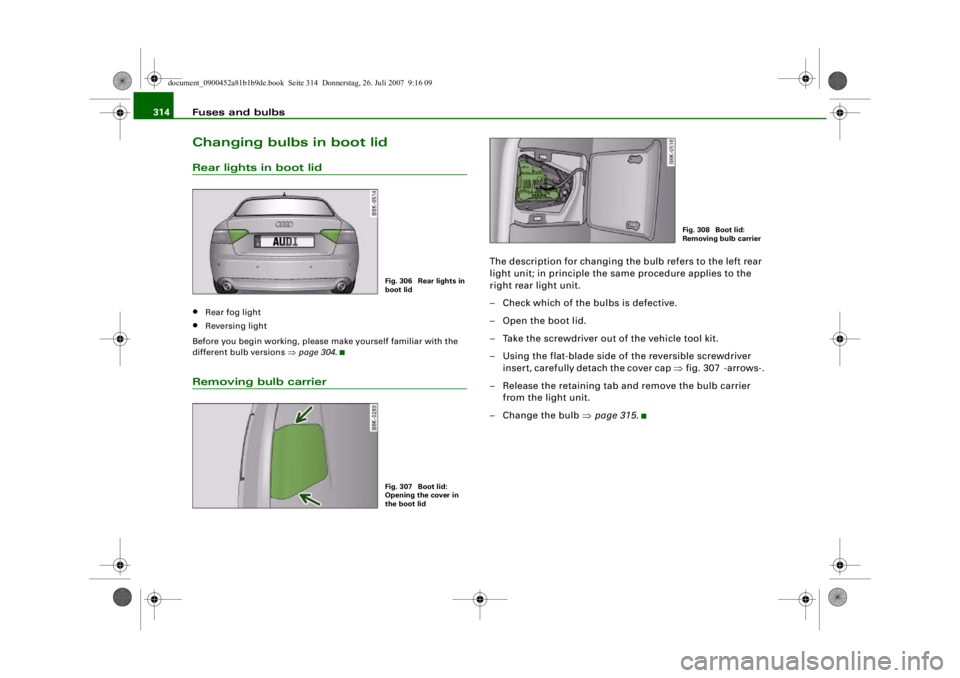
The description for changing the bulb refers to the left rear
light unit; in principle the same procedure applies to the
right rear light unit.
– Check which of the bulbs is defective.
– Open the boot lid.
– Take the screwdriver out of the vehicle tool kit.
– Using the flat-blade side of the reversible screwdriver
insert, carefully detach the cover cap ⇒fig. 307 -arrows-.
– Release the retaining tab and remove the bulb carrier from the light unit.
– Change the bulb ⇒page 315 .
Fig. 306 Rear lights in
boot lidFig. 307 Boot lid:
Opening the cover in
the boot lid
Fig. 308 Boot lid:
Removing bulb carrier
document_0900452a81b1b9de.book Seite 314 Donnerstag, 26. Juli 2007 9:16 09
--4 -
-T
-+
•
+-
•
Page 317 of 342

Fuses and bulbs315
Controls
Safety
Driving tips
General maintenance
Self-help
Technical data
Changing bulb / installing bulb carrier– Renew the defective bulb (pull to remove from plug-in
holder or turn to remove from bayonet holder)
⇒page 305 .
– Insert the bulb carrier into the rear light. Make sure you hear the retaining tab click into place.
– Fit the cover back in the interior trim so that it engages.
– Put the screwdriver back into the tool kit.
– Make sure that all bulbs for the rear lights are working.
Applies to vehicles: with halogen main beam headlightsNumber plate lightRemoving number plate light
– Take the screwdriver out of the vehicle tool kit ⇒page 283.
– Insert the flat-blade side of the reversible screwdriver insert into the slot on the number plate light ⇒fig. 310.
– Using the screwdriver, start by pressing the number plate light to the right -arrow 1- and then pull the number
plate light downwards from th is position -arrow 2- and
out of the opening.
Fig. 309 Bulb carrier
Fig. 310 Boot lid:
Removing number
plate lightFig. 311 Number plate
light: Retaining
element
document_0900452a81b1b9de.book Seite 315 Donnerstag, 26. Juli 2007 9:16 09
--4 -
-T
-+ +-
•