2008 AUDI S4 reset
[x] Cancel search: resetPage 136 of 342

adaptive cruise control (ACC)
134
WARNING
When setting the distance, the driv er is responsible for adhering
to the laws and regulations which apply in the country he is trav-
elling in.Driver messagesApplies to vehicles: with adaptive cruise controlMessages in the instrument cluster
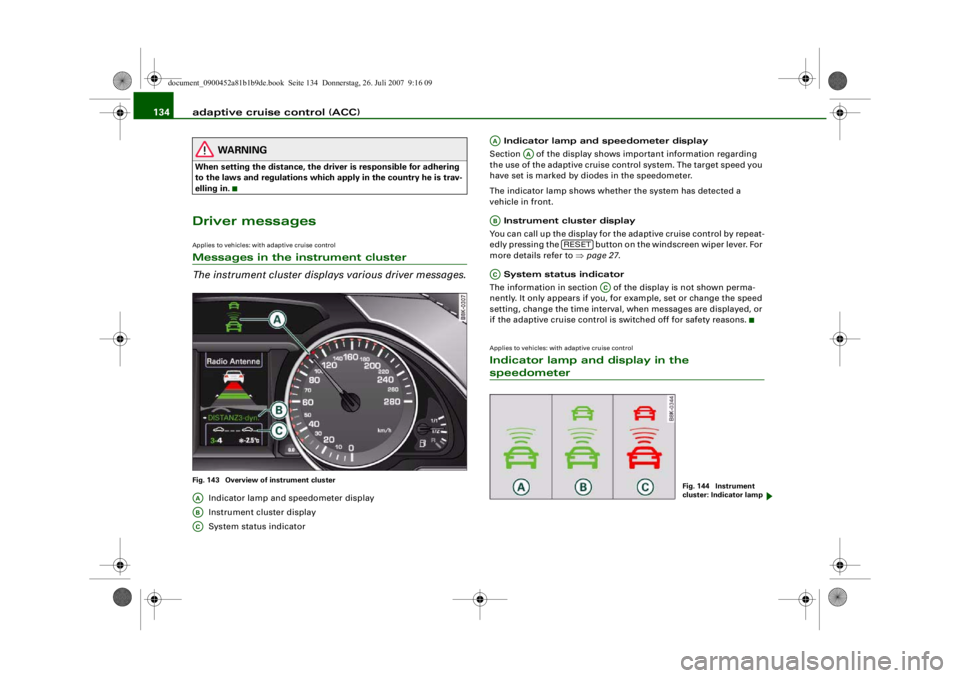
The instrument cluster displa ys various driver messages.Fig. 143 Overview of instrument cluster
Indicator lamp and speedometer display
Instrument cluster display
System status indicator Indicator lamp and speedometer display
Section of the display shows important information regarding
the use of the adaptive cruise control system. The target speed you
have set is marked by diodes in the speedometer.
The indicator lamp shows whether the system has detected a
vehicle in front.
Instrument cluster display
You can call up the display for the adaptive cruise control by repeat-
edly pressing the button on the windscreen wiper lever. For
more details refer to ⇒ page 27.
System status indicator
The information in section of the display is not shown perma-
nently. It only appears if you, for example, set or change the speed
setting, change the time interval, when messages are displayed, or
if the adaptive cruise control is switched off for safety reasons.
Applies to vehicles: with adaptive cruise controlIndicator lamp and display in the speedometer
AAABAC
AA
AA
AB
RESET
AC
AC
Fig. 144 Instrument
cluster: Indicator lamp
document_0900452a81b1b9de.book Seite 134 Donnerstag, 26. Juli 2007 9:16 09
--4 -
-T
-+
•
+-
~ ~
---
-~
--
~ - - --
-
~
~
~
® ® ©
Page 137 of 342

adaptive cruise control (ACC)135
Controls
Safety
Driving tips
General maintenance
Self-help
Technical data
Target speed
The target speed set by the driver is indicated by a red diode in the
speedometer.
If the speed setting is between two graduations on the speedom-
eter dial, the two closest diodes will both light up
⇒fig. 143.
It is only possible to set target speeds ranging from 30 to 200 km/h.
This speed range is illuminated slightly by the diodes on the speed-
ometer dial.
Indicator lamp (symbol)
•
No vehicle in front: The green indicator lamp ⇒ page 134,
fig. 144 shows that the adaptive crui se control system is in cruise
mode and that there is no vehicle in front. It maintains the stored
target speed.
•
Vehicle in front: The green indicator lamp shows that the
system has detected a vehicle in front. The speed is adapted to the
vehicle in front. The adaptive cruise control system accelerates and
brakes the vehicle automatically.
•
Driver intervention prompt: When the red indicator lamp
flashes , this is a warning for the driv er to intervene. The driver
has to brake the vehicle with the foot brake. This warning lamp will
always appear when the adaptive cruise control system alone is not
able to brake the vehicle sufficiently to maintain a safe distance to
a vehicle in front. An audible alarm (warning tone) will also sound
when the lamp starts to flash. For further information on the driver
intervention prompt ⇒page 138 .Note
•
If you exceed the target speed by using the accelerator, the
driver intervention prompt will not be accompanied by a warning
tone. The indicator lamp shown in the speedometer will also switch
off if the target speed is exceeded.
•
You can change the volume of the warning tone on the sound
system or MMI* ⇒ page 139, “Setting the warning tone volume and
driving program”.
Applies to vehicles: with adaptive cruise controlInstrument cluster displayRepeatedly press the button on the windscreen wiper lever
to select whether you wish to display information regarding the on-
board computer, the navigation sy stem* or the adaptive cruise
control in this section of the display screen.
Vehicle image
Distance
System status
Vehicle image
The vehicle image will show you whether the system has detected a
vehicle in front.•
Vehicle outlined : No vehicle in front
•
Vehicle in white: A vehicle in front has been detected
•
Vehicle in red: Driver intervention prompt
Distance
The arrows and scale indicate the distance to the vehicle in front.
•
No vehicle in front: If there is no vehicle in front, no arrows will
be shown.
AA
AA
AB
AB
AC
AC
Fig. 145 Instrument
cluster: Display
RESET
AAABACAAAB
document_0900452a81b1b9de.book Seite 135 Donnerstag, 26. Juli 2007 9:16 09
--4 -
-T
-+ +-
[I]
Page 144 of 342

adaptive cruise control (ACC)
142Applies to vehicles: with adaptive cruise controlStationary vehiclesIf a vehicle detected by the ACC system turns off or changes lane
and another stationary vehicle is loca ted in front of that vehicle, the
ACC system will not react to the stationary vehicle ⇒fig. 154 and
⇒ fig. 155.
Audi braking guardApplies to vehicles: with adaptive cruise controlDescription
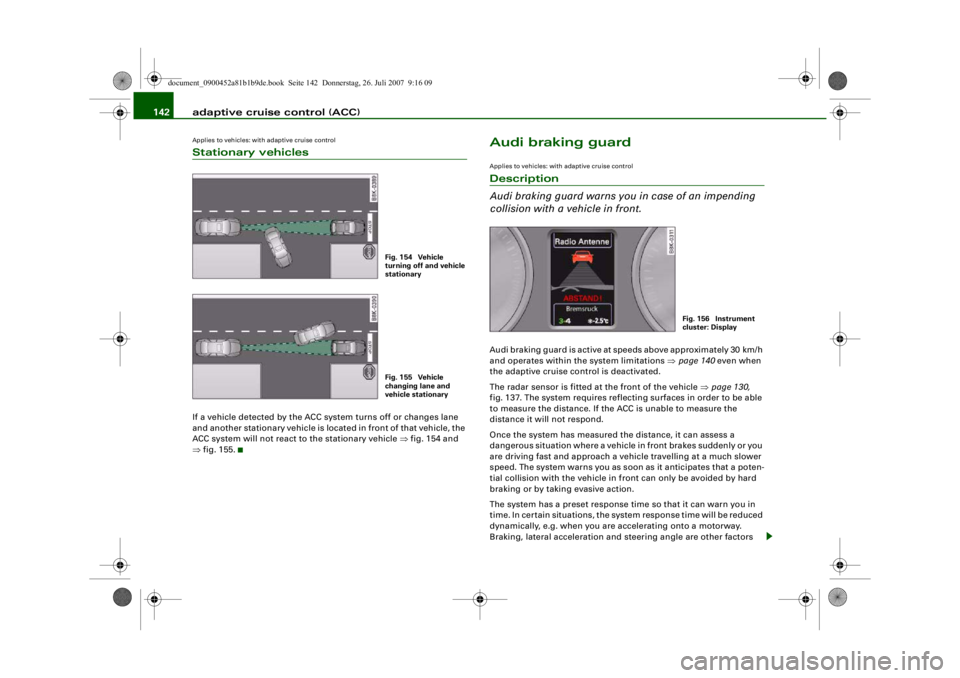
Audi braking guard warns you in case of an impending
collision with a vehicle in front.Audi braking guard is active at speeds above appr oximately 30 km/h
and operates within the system limitations ⇒ page 140 even when
the adaptive cruise control is deactivated.
The radar sensor is fitted at the front of the vehicle ⇒page 130,
fig. 137. The system requires reflecting surfaces in order to be able
to measure the distance. If the ACC is unable to measure the
distance it will not respond.
Once the system has measured the distance, it can assess a
dangerous situation where a vehicle in front brakes suddenly or you
are driving fast and approach a vehicle travelling at a much slower
speed. The system warns you as soon as it anticipates that a poten-
tial collision with the vehicle in front can only be avoided by hard
braking or by taking evasive action.
The system has a preset response time so that it can warn you in
time. In certain situations, the system response time will be reduced
dynamically, e.g. when you are accelerating onto a motorway.
Braking, lateral acceleration and steering angle are other factors
Fig. 154 Vehicle
turning off and vehicle
stationaryFig. 155 Vehicle
changing lane and
vehicle stationary
Fig. 156 Instrument
cluster: Display
document_0900452a81b1b9de.book Seite 142 Donnerstag, 26. Juli 2007 9:16 09
--4 -
-T
-+ +-
•
Page 148 of 342

Audi lane assist
146Indicator lamp in instrument cluster Active: The green indicator lamp confirms that the system is fully
functional. You will be warned if you are about to cross the lane
markings detected by the system. Inactive: The yellow warning lamp indicates that the system is
switched on. However, you will not be warned if you cross the lane
markings. This can have the following causes:•
There is only one or no lane marking.
•
The system cannot detect the lane markings (e.g. due to snow,
dirt, wet conditions or adverse light).
•
There are more than two lane markings in the lane you are
driving in (e.g. in roadwork sections).
•
The vehicle's speed is below 65 km/h, the speed at which the lane
assist system is activated.
•
The lane is narrower than 2.5 m or wider than 5 m.
•
The bend is too tight.Note
•
Make sure that the camera window ⇒page 145, fig. 159 is not
covered with stickers or similar objects.
•
Always keep the camera window clean. Usually it should suffice
to operate the windscreen wipers.
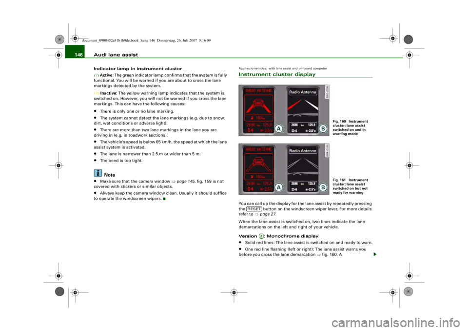
Applies to vehicles: with lane assist and on-board computerInstrument cluster displayYou can call up the display for the lane assist by repeatedly pressing
the button on the windscreen wiper lever. For more details
refer to ⇒page 27 .
When the lane assist is switched on, two lines indicate the lane
demarcations on the left and right of your vehicle.
Version : Monochrome display•
Solid red lines: The lane assist is switched on and ready to warn.
•
One red line flashing (left or right): The lane assist warns you
before you cross the lane demarcation ⇒fig. 160, A
Fig. 160 Instrument
cluster: lane assist
switched on and in
warning modeFig. 161 Instrument
cluster: lane assist
switched on but not
ready for warning
RESET
AA
document_0900452a81b1b9de.book Seite 146 Donnerstag, 26. Juli 2007 9:16 09
--4 -
-T
-+
rn
+-
•
Page 168 of 342

Automatic gearbox
166
WARNING
Please note that if the road sur face is slippery or wet, the kick-
down feature could ca use the driving wheels to spin, which could
result in skidding.Applies to vehicles: with multitronic® or tiptronicDynamic gear control program (DCP)
The automatic gearbox is controlled electronically.The vehicle is equipped with an electronically controlled gearbox.
The gear ratios are selected automatically according to preset gear-
shift programmes.
When you drive at moderate speeds the gearbox will select the most
economical shift programme. It will then change up early and delay
the downshifts to gi ve better fuel economy.
If you drive at higher speeds with heavy acceleration, if you open the
throttle quickly, or if you use the kick-down or the car's maximum
speed, the gearbox will automaticall y select the more “sporty” shift
programmes.
The gearbox is self-adapting, and continuously selects the most
suitable shift programme. At the same time, the driver can also
make the gearbox switch to a more "sporty" programme by pressing
the accelerator quickly. Depending on road speed, this makes the
gearbox shift down early into a lower gear ratio for more rapid accel-
eration (for instance to pass another vehicle), without having to
press the accelerator all the way down into the kick-down position.
After the gearbox has shifted back up it returns to the original
programme, depending on your style of driving.
Vehicles with multitronic® gear box: The gearbox continuously
adapts the gear ratios on uphill gradients. If the brake pedal is
pressed on a downhill gradient the gearbox automatically shifts to
a lower gear ratio. This increases the engine braking effect. Vehicles with tiptronic gearbox:
The gearbox adapts the gearshifts
for uphill and downhill gradients. This prevents the gearbox from
shifting up and down unnecessarily on uphill gradients.
Applies to vehicles: with multitronic® or tiptronicManual gear selection (tiptronic mode)
With the manual shift programme (tiptronic) the driver
can manually select pre-programmed gears.Switching over to the manual programme
– From position D, push the selector lever to the right. As soon as the automatic gearbox has changed over to this
programme, the display will show the selected gear.
Fig. 180 Centre
console: Manual gear
selection (tiptronic
mode)Fig. 181 Display:
Manual gear selection
(tiptronic mode)
document_0900452a81b1b9de.book Seite 166 Donnerstag, 26. Juli 2007 9:16 09
--4 -
-T
•
•
-+ +-
Page 265 of 342

Checking and topping up fluids263
Controls
Safety
Driving tips
General maintenance
Self-help
Technical data
Changing brake fluid
When required, the brake fluid should be changed by a
competent mechanic with the proper equipment.Brake fluid gradually absorbs moisture from the atmosphere. If the
water content in the brake fluid is too high, this may cause corrosion
in the brake system over time. In addition, the boiling point of the
brake fluid will be considerably reduced. This could adversely affect
the braking ability in certain circumstances.
For this reason the brake fluid must be changed periodically.
Your vehicle's Service Schedule will tell you when the brake fluid has
to be changed.
It is advisable to have the brake fluid changed as part of a regular
Inspection Service at your Audi workshop. They are familiar with the
procedure and have the necessary special tools and spare parts as
well as the proper facilities for disposing of the old fluid.
Use only the genuine brake fluid specified by the factory Qualified
workshops know that the brake fluid “DOT 4” is approved by Audi.
The brake fluid must be fresh and unused.
WARNING
•
Brake fluid is poisonous; store it in the sealed original container
in a safe place out of reach of children.
•
Heavy use of the brakes may caus e a vapour lock if the brake
fluid is left in the system for too long. This would seriously affect
the efficiency of the brakes and th e safety of the car – risk of acci-
dent.Caution
Please note that brake fluid will attack the paintwork on contact.
For the sake of the environment
If the fluid has to be drained out of the brake system, use an appro-
priate container to catch the used brake fluid and dispose of it in the
proper manner.BatteryGeneral notes
All work on batteries requires specialist knowledge.The battery is virtually maintenance-free. It is checked as part of the
Inspection Service.
We recommend that you replace a ba ttery once it is older than 5
years.
When an airbag is triggered, the battery will, under certain circum-
stances, be disconnected from the on-board power supply for
safety reasons ⇒ in “General notes on airbag system” on
page 201 .
Disconnecting the battery
If the battery is disconnected, some of the vehicle's functions will
become inoperative (e.g. electric windows). These functions will
require resetting after the battery is reconnected. For this reason,
the battery should only be disconnected from the vehicle's electrical
system when absolutely necessary.
If the vehicle is not used for long periods
If you do not drive your vehicle for a period of several days or weeks,
the power management will gr adually shut off the on-board
systems one by one, or reduce the amount of current they are using.
This limits the amount of power consumed and helps to ensure reli-
able starting even after a long period ⇒page 226 .
document_0900452a81b1b9de.book Seite 263 Donnerstag, 26. Juli 2007 9:16 09
--4 -
-T
•
-+ +-
CD
Page 303 of 342

Fuses and bulbs301
Controls
Safety
Driving tips
General maintenance
Self-help
Technical data
The seats with electrical adjustment are protected by circuit
breakers
. These reset automatically after a few seconds when the
overload has been corrected.
Fuse list
Fuse list Fuse list
No.
Electrical equipment
amps
Fuse carrier (black)
1
Dynamic steering
5
2
Clutch sensor
5
3
Garage door opener
5
4
Audi lane assist
10
5
Air conditioner
5
6
Headlight range control (right)
5
7
Headlight range control (left)
5
8
Control unit 1 for vehicle's electrical system
5
9
Interior mirrors
5
10
Selector gate
5
11
Heated washer jets
5
12
Air conditioner
5
No.
Electrical equipment
amps
Fuse carrier (brown)
1
Vacant
2
Clutch sensor
5
3
Fuel pump (diesel/petrol)
20/25
4
Auxiliary water pump (3.2 FSI)
5
5
Seat heating (left-side) with/without seat venti-
lation
30
6
Electronic stab
ilisation program
10
7
Horn
25
8
Electric window motor (left door)
30
9
Wiper motor
30
10
Electronic stabilisation program
25
11
Door control unit (driver's side)
15
12
Rain and light sensor
5
No.
Electrical equipment
amps
Fuse carrier (red)
1
Vacant
2
Vacant
3
Lumbar support
10
4
Dynamic steering
35
5
Interior light
5
6
Control unit 1 for vehicle's electrical system
35
7
Control unit 1 for vehicle's electrical system
30
8
Control unit 1 for vehicle's electrical system
30
9
Tilting panorama roof/sun roof
20
10
Control unit 1 for vehicle's electrical system
30
11
Vacant
12
Convenience electronics
5
No.
Electrical equipment
amps
document_0900452a81b1b9de.book Seite 301 Donnerstag, 26. Juli 2007 9:16 09
--4 -
-T
1111
-
-
1111
--
1111
-
-
1111
-
-+
1111
--
+-
1111
--
1111
--
-
1111
-
-
1111
--
1111
--
•
~
Page 304 of 342

Fuses and bulbs
302Fuses on the passenger's sideSome of the items listed are only fitted on certain models or are
optional extras.
Please note that the following li st, while correct at the time of
printing, is subject to alterations. If discrepancies should occur,
please refer to the sticker on the inside of the fuse cover for the
correct information for your vehicle.
The seats with electrical adjustment are protected by circuit
breakers . These reset automatically after a few seconds when the
overload has been corrected.
Fuse list Fuse listNo.
Electrical equipment
amps
Fuse carrier (black)1
Vacant
2
Vacant
3
Vacant
4
Vacant
5
Steering column switch module
5
6
Electronic Stabilisation Program
5
Fig. 285 Diagram of
fuse box (left-hand
drive vehicle)
7
Diagnostic connector
5
8
Gateway (diagnostic in
terface for data bus)
5
9
Vacant
10
Vacant
11
Vacant
12
Vacant
No.
Electrical equipment
amps
Fuse carrier (brown)1
CD drive
5
2
Switch module for Audi drive select
5
3
MMI/Radio
10/20
4
Light switch
5
5
Control unit for instrument cluster
5
6
Ignition lock
5
7
Vacant
8
Air conditioner blower
40
9
Steering column lock
5
10
Air conditioner
10
11
Diagnostic connector
10
12
Steering column switch module
5
No.
Electrical equipment
amps
document_0900452a81b1b9de.book Seite 302 Donnerstag, 26. Juli 2007 9:16 09
-+ ~
--11-
..
-
..
-
..
-
..
-
..
..
..
..
..
..
..
..
..
..
..
--4 -
-
-
T
-
-
-
-
-
+-
-
-
-
-
-
•
4-
---r