2008 AUDI A5 navigation system
[x] Cancel search: navigation systemPage 3 of 313
ForewordThank you for choosing the Audi A5.
The new Audi A5 combines the latest technology with numerous features for your comfort and
convenience. To help you get the best out of these features in everyday use, we recommend that
you read this Manual carefully so you can quickly become familiar with your vehicle in detail.
As well as information on how to use the controls and equipment, the Owner's Manual contains
important notes on care and maintenance. These are relevant to your safety and will help preserve
your car's value. The Manual also offers useful driving tips and advice, together with some sugges-
tions on how to drive your car with minimum impact on the environment.
In addition to this Owner's Manual, the Service Wallet also includes the Service Schedule for your
vehicle. This booklet contains important information on Audi service requirements and lists the
vehicle's fuel consumption figures. The Service Wallet also includes operating manuals for
optional on-board systems such as the radio, navigation and telephone. We recommend that you
keep the Service Wallet in the car at all times.
Should you have any further questions regarding your car or if you suspect that your owner's liter-
ature is not complete, please contact your Audi dealer or importer. They are always glad to answer
your queries and note any suggestions you may have.
We wish you safe and enjoyable motoring with your Audi A5.
AUDI AG
document_0900452a8179700c.book Seite 1 Donnerstag, 22. März 2007 10:19 10
Page 22 of 313
Driver information system 20Driver information systemIntroductionGeneral notes
The driver information system in the instrument cluster
shows you the status of various on-board systems at a
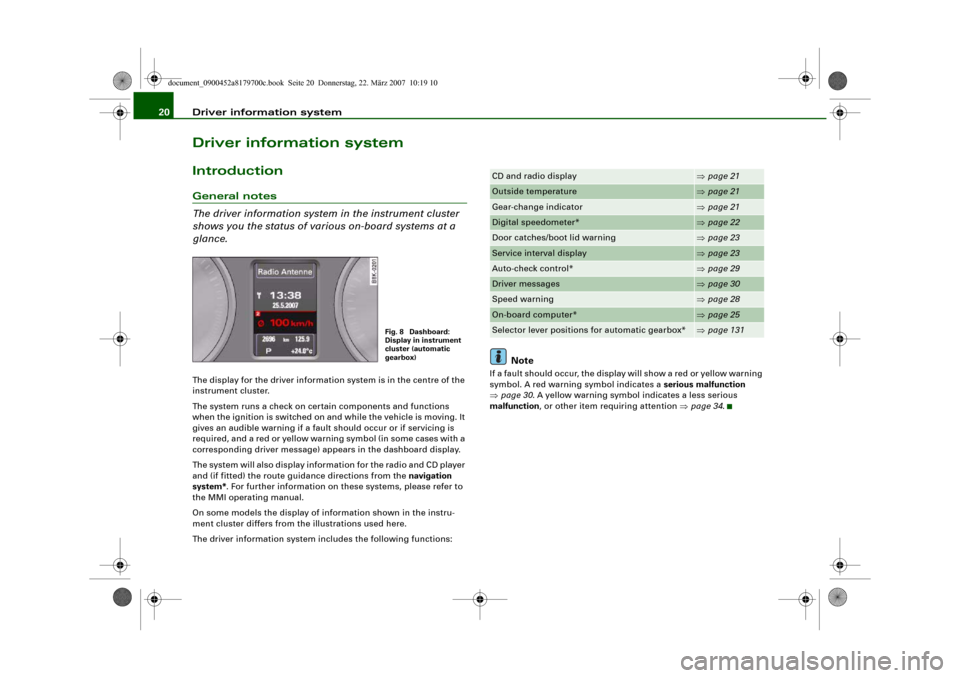
glance.The display for the driver information system is in the centre of the
instrument cluster.
The system runs a check on certain components and functions
when the ignition is switched on and while the vehicle is moving. It
gives an audible warning if a fault should occur or if servicing is
required, and a red or yellow warning symbol (in some cases with a
corresponding driver message) appears in the dashboard display.
The system will also display information for the radio and CD player
and (if fitted) the route guidance directions from the navigation
system*. For further information on these systems, please refer to
the MMI operating manual.
On some models the display of information shown in the instru-
ment cluster differs from the illustrations used here.
The driver information system includes the following functions:
Note
If a fault should occur, the display will show a red or yellow warning
symbol. A red warning symbol indicates a serious malfunction
⇒page 30. A yellow warning symbol indicates a less serious
malfunction, or other item requiring attention ⇒page 34.
Fig. 8 Dashboard:
Display in instrument
cluster (automatic
gearbox)
CD and radio display
⇒page 21
Outside temperature
⇒page 21
Gear-change indicator
⇒page 21
Digital speedometer*
⇒page 22
Door catches/boot lid warning
⇒page 23
Service interval display
⇒page 23
Auto-check control*
⇒page 29
Driver messages
⇒page 30
Speed warning
⇒page 28
On-board computer*
⇒page 25
Selector lever positions for automatic gearbox*
⇒page 131
document_0900452a8179700c.book Seite 20 Donnerstag, 22. März 2007 10:19 10
Page 29 of 313
Driver information system27
Controls
Safety
Driving tips
General maintenance
Self-help
Technical data eter and navigation system*. Press the Reset button briefly to
switch back and forward between these displays.
Resetting figures to zero
To cancel one of the computer readings individually, select the
required function and press the RESET button for at least one
second. The following values can be reset to zero individually using
the Reset button:
•
Average fuel consumption
•
Average speed
•
Driving time
•
Distance covered
You can also cancel all the values in the single journey memory or
the total journey memory at the same time ⇒page 27.Note
The information in the memory is cancelled if the battery is
disconnected.
Applies to vehicles: with on-board computerBasic settings for the on-board computer
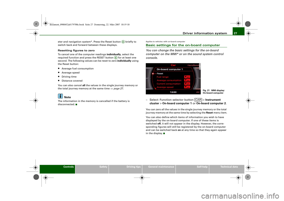
You can change the basic settings for the on-board
computer on the MMI* or on the sound system control
console.– Select: Function selector button > Instrument
cluster > On-board computer 1 or On-board computer 2.You can zero all the values in the single journey memory or the total
journey memory at the same time by selecting the Reset menu item.
You can also define which items of information you wish to have
displayed by the on-board computer. If one of these items is
switched off, it will not appear in the display. However, the corre-
sponding figures will still be registered by the on-board computer
and can be switched back on at any time so that they again appear
in the display.
AB
AB
Fig. 21 MMI display:
On-board computer
CAR
document_0900452a8179700c.book Seite 27 Donnerstag, 22. März 2007 10:19 10
Page 81 of 313
Seats and storage79
Controls
Safety
Driving tips
General maintenance
Self-help
Technical data
Applies to vehicles: with stretch netStretch net / retaining net
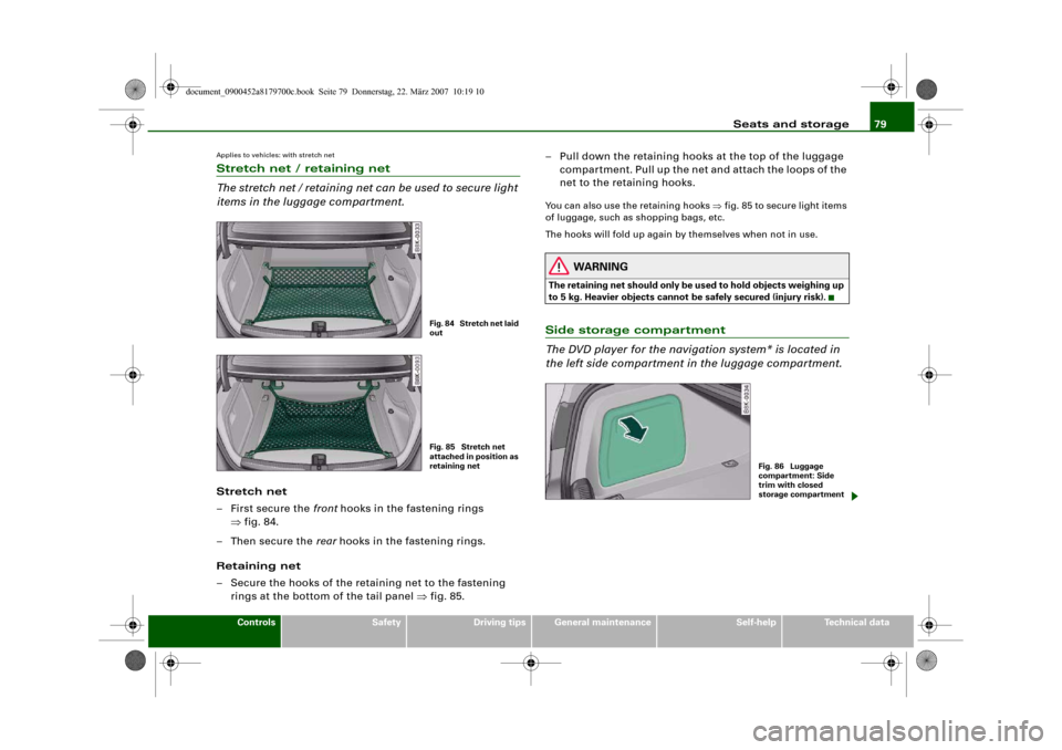
The stretch net / retaining net can be used to secure light
items in the luggage compartment.Stretch net
– First secure the front hooks in the fastening rings
⇒fig. 84.
–Then secure the rear hooks in the fastening rings.
Retaining net
– Secure the hooks of the retaining net to the fastening
rings at the bottom of the tail panel ⇒fig. 85.– Pull down the retaining hooks at the top of the luggage
compartment. Pull up the net and attach the loops of the
net to the retaining hooks.
You can also use the retaining hooks ⇒fig. 85 to secure light items
of luggage, such as shopping bags, etc.
The hooks will fold up again by themselves when not in use.
WARNING
The retaining net should only be used to hold objects weighing up
to 5 kg. Heavier objects cannot be safely secured (injury risk).Side storage compartment
The DVD player for the navigation system* is located in
the left side compartment in the luggage compartment.
Fig. 84 Stretch net laid
outFig. 85 Stretch net
attached in position as
retaining net
Fig. 86 Luggage
compartment: Side
trim with closed
storage compartment
document_0900452a8179700c.book Seite 79 Donnerstag, 22. März 2007 10:19 10
Page 82 of 313
Seats and storage 80
– To open the storage compartment, pull the handle
⇒page 79, fig. 86.DVD player for navigation system*
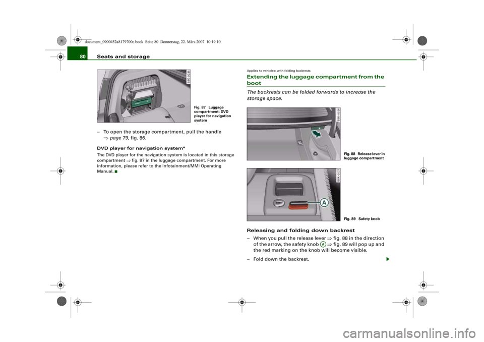
The DVD player for the navigation system is located in this storage
compartment ⇒fig. 87 in the luggage compartment. For more
information, please refer to the Infotainment/MMI Operating
Manual.
Applies to vehicles: with folding backrestsExtending the luggage compartment from the boot
The backrests can be folded forwards to increase the
storage space.Releasing and folding down backrest
– When you pull the release lever ⇒fig. 88 in the direction
of the arrow, the safety knob ⇒fig. 89 will pop up and
the red marking on the knob will become visible.
– Fold down the backrest.
Fig. 87 Luggage
compartment: DVD
player for navigation
system
Fig. 88 Release lever in
luggage compartmentFig. 89 Safety knob
AA
document_0900452a8179700c.book Seite 80 Donnerstag, 22. März 2007 10:19 10
Page 277 of 313

Fuses and bulbs275
Controls
Safety
Driving tips
General maintenance
Self-help
Technical data
Fuse list for luggage compartment– Remove the trim.
– Open the fuse cover.Fuse listFuse list
Fuse listNo.
Electrical equipment
amps
Fuse carrier (black)
1
Vacant
2
Control unit for trailer
15
3
Control unit for trailer
20
4
Control unit for trailer
20
5
Electronic parking brake
5
6
Electronic suspension control
15
7
Electronic parking brake
30
8
Control unit 2 for vehicle's electrical system
30
9
Vacant
Fig. 256 Diagram of
fuse panel
10
Control unit 2 for vehicle's electrical system
30
11
Control unit 2 for vehicle's electrical system
20
12
Vacant
No.
Electrical equipment
amps
Fuse carrier (brown)
1
Electrical socket
15
2
Vacant
3
Radio/navigation
7.5
4
Control unit for digital sound system
30
5
MMI
5
6
Door control unit (driver's side)
30
7
Electronic parking brake
30
8
Seat heating, rear
30
9
Electric window (right)
30
10
Remote control receiver for auxiliary heating
5
11
Door control unit (passenger side)
15
12
Control unit for reversing camera
5
No.
Electrical equipment
amps
Fuse carrier (red)
1
Socket, centre console, rear
15
2
Socket, centre console, front
15
3
Socket, luggage compartment
15
No.
Electrical equipment
amps
document_0900452a8179700c.book Seite 275 Donnerstag, 22. März 2007 10:19 10