2008 AUDI A5 window
[x] Cancel search: windowPage 55 of 313
Doors and windows53
Controls
Safety
Driving tips
General maintenance
Self-help
Technical data
WARNING
Take care when closing the tilting panorama roof. Careless or
uncontrolled use can cause injuries. For this reason, always take
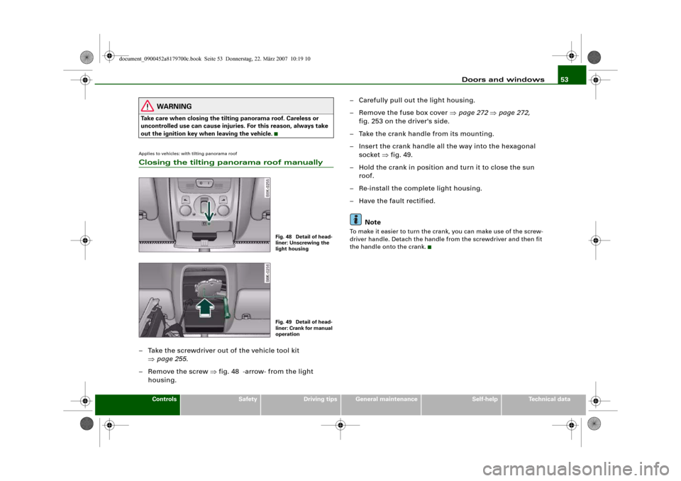
out the ignition key when leaving the vehicle.Applies to vehicles: with tilting panorama roofClosing the tilting panorama roof manually– Take the screwdriver out of the vehicle tool kit
⇒page 255.
– Remove the screw ⇒fig. 48 -arrow- from the light
housing.– Carefully pull out the light housing.
– Remove the fuse box cover ⇒page 272 ⇒page 272,
fig. 253 on the driver's side.
– Take the crank handle from its mounting.
– Insert the crank handle all the way into the hexagonal
socket ⇒fig. 49.
– Hold the crank in position and turn it to close the sun
roof.
– Re-install the complete light housing.
– Have the fault rectified.
Note
To make it easier to turn the crank, you can make use of the screw-
driver handle. Detach the handle from the screwdriver and then fit
the handle onto the crank.
Fig. 48 Detail of head-
liner: Unscrewing the
light housingFig. 49 Detail of head-
liner: Crank for manual
operation
document_0900452a8179700c.book Seite 53 Donnerstag, 22. März 2007 10:19 10
Page 63 of 313
Lights and vision61
Controls
Safety
Driving tips
General maintenance
Self-help
Technical data The reading lights are switched on and off with the switches
.
Clear visionSun visors
The sun visors can improve visibility and contribute to
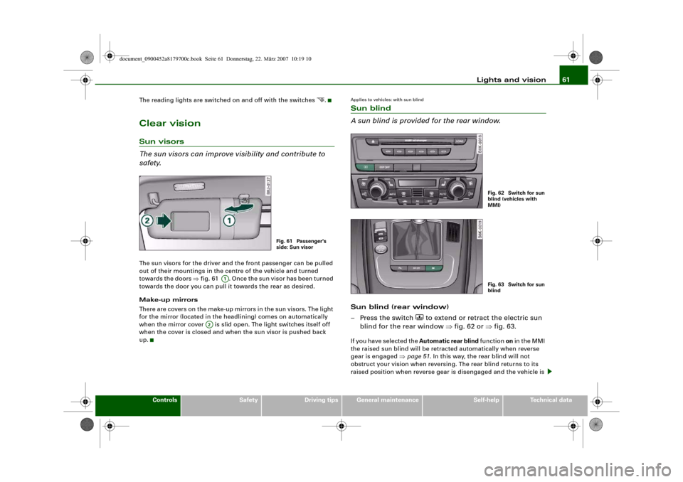
safety.The sun visors for the driver and the front passenger can be pulled
out of their mountings in the centre of the vehicle and turned
towards the doors ⇒fig. 61 . Once the sun visor has been turned
towards the door you can pull it towards the rear as desired.
Make-up mirrors
There are covers on the make-up mirrors in the sun visors. The light
for the mirror (located in the headlining) comes on automatically
when the mirror cover is slid open. The light switches itself off
when the cover is closed and when the sun visor is pushed back
up.
Applies to vehicles: with sun blindSun blind
A sun blind is provided for the rear window.Sun blind (rear window)
– Press the switch
to extend or retract the electric sun
blind for the rear window ⇒fig. 62 or ⇒fig. 63.
If you have selected the Automatic rear blind function on in the MMI
the raised sun blind will be retracted automatically when reverse
gear is engaged ⇒page 51. In this way, the rear blind will not
obstruct your vision when reversing. The rear blind returns to its
raised position when reverse gear is disengaged and the vehicle is
Fig. 61 Passenger's
side: Sun visor
A1
A2
Fig. 62 Switch for sun
blind (vehicles with
MMI)Fig. 63 Switch for sun
blind
document_0900452a8179700c.book Seite 61 Donnerstag, 22. März 2007 10:19 10
Page 64 of 313
Lights and vision 62driven forwards at a speed above about 15 km/h. The current setting
is automatically stored and assigned to the remote control key.
If the rear blind was rolled in automatically when reversing and then
the ignition was switched off and on again, the blind will not roll
back out again when you select a forward gear and the speed
exceeds 15 km/h. You will then have to press the button
on the
centre console to extend the blind again.
The sun blind for the rear window switches off automatically when
it reaches the end position. It can be made to move in the other
direction before it reaches its end position by briefly pressing the
switch a second time. If the ignition is turned off while the blind is
still moving, it continues until it reaches the end position before
switching off.
Note
•
An overload cut-out may be activated if the sun blind is operated
repeatedly. There will then be a short delay before the blind can be
operated again.
•
As the material of the sun blind is less flexible at low tempera-
tures the electric actuator is switched off when the temperature in
the car is below -5°C. The blind can only be operated when the
temperature in the car's interior rises above this level.
Windscreen wipersWindscreen wipers
The windscreen wiper lever controls the windscreen
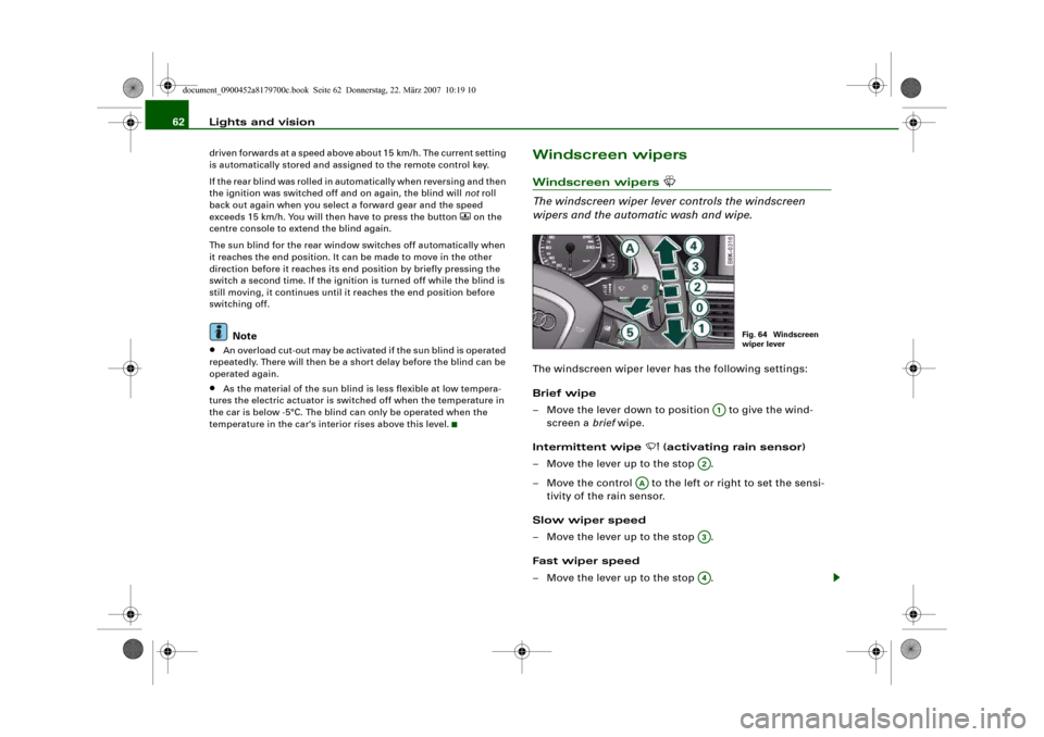
wipers and the automatic wash and wipe.The windscreen wiper lever has the following settings:
Brief wipe
– Move the lever down to position to give the wind-
screen a brief wipe.
Intermittent wipe
(activating rain sensor)
– Move the lever up to the stop .
– Move the control to the left or right to set the sensi-
tivity of the rain sensor.
Slow wiper speed
– Move the lever up to the stop .
Fast wiper speed
– Move the lever up to the stop .
Fig. 64 Windscreen
wiper lever
A1
A2
AA
A3A4
document_0900452a8179700c.book Seite 62 Donnerstag, 22. März 2007 10:19 10
Page 67 of 313
Lights and vision65
Controls
Safety
Driving tips
General maintenance
Self-help
Technical data when they are in the service position you will also avoid damaging
the paintwork on the bonnet.
•
off - the windscreen wipers will be moved back to their original
position.Caution
Never move the vehicle with the front wiper arms in a raised posi-
tion as they are automatically moved back to their normal park posi-
tion above a speed of 6 km/h. The paintwork on the bonnet may be
damaged as a result.
Note
•
You can also use the service position, for example, if you want to
fix a cover over the windscreen in the winter to keep it clear of ice.
•
The service position is automatically set to off when you operate
the windscreen wiper lever or the road speed exceeds 6 km/h.
Changing wiper blades
Good wiper blades are essential for clear vision.Taking off the wiper blade
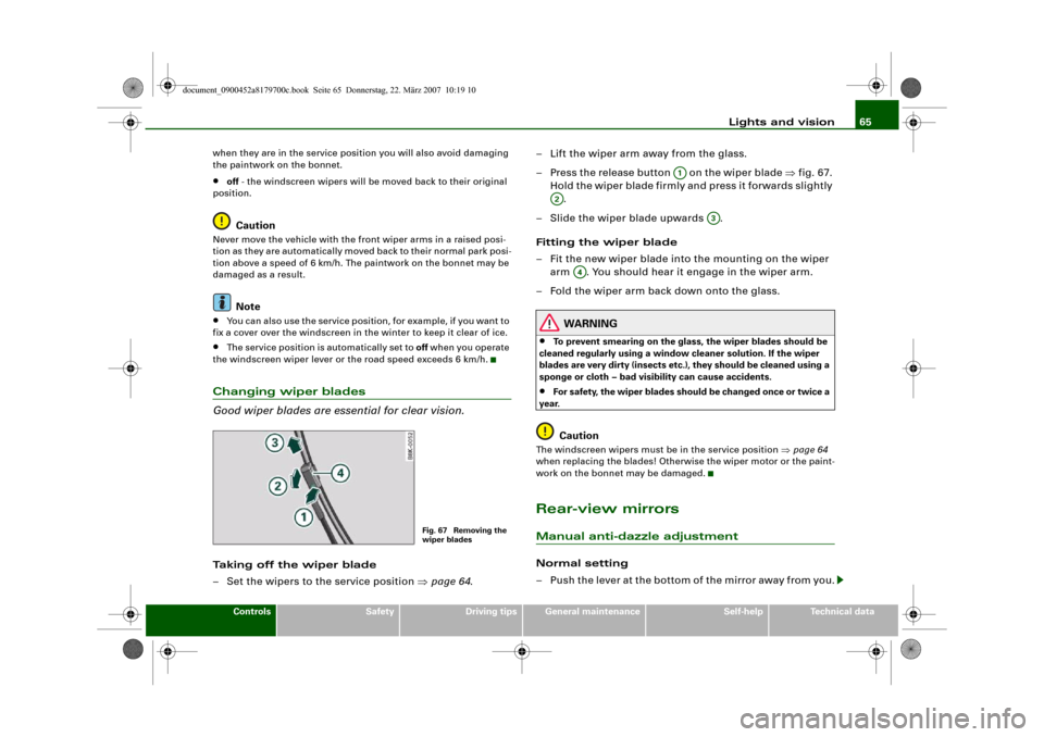
– Set the wipers to the service position ⇒page 64.– Lift the wiper arm away from the glass.
– Press the release button on the wiper blade ⇒fig. 67.
Hold the wiper blade firmly and press it forwards slightly
.
– Slide the wiper blade upwards .
Fitting the wiper blade
– Fit the new wiper blade into the mounting on the wiper
arm . You should hear it engage in the wiper arm.
– Fold the wiper arm back down onto the glass.
WARNING
•
To prevent smearing on the glass, the wiper blades should be
cleaned regularly using a window cleaner solution. If the wiper
blades are very dirty (insects etc.), they should be cleaned using a
sponge or cloth – bad visibility can cause accidents.
•
For safety, the wiper blades should be changed once or twice a
year.Caution
The windscreen wipers must be in the service position ⇒page 64
when replacing the blades! Otherwise the wiper motor or the paint-
work on the bonnet may be damaged.Rear-view mirrorsManual anti-dazzle adjustmentNormal setting
– Push the lever at the bottom of the mirror away from you.
Fig. 67 Removing the
wiper blades
A1
A2
A3
A4
document_0900452a8179700c.book Seite 65 Donnerstag, 22. März 2007 10:19 10
Page 68 of 313
Lights and vision 66
Anti-dazzle setting
– Pull the lever at the bottom of the mirror towards you.Applies to vehicles: with automatic anti-dazzle adjustment for interior mirrorAutomatic anti-dazzle adjustment
The automatic anti-dazzle function can be switched on
and off as desired.Switching off anti-dazzle function
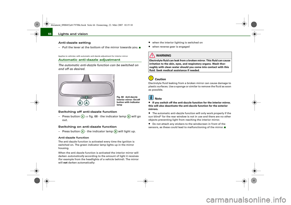
– Press button ⇒fig. 68 - the indicator lamp will go
out.
Switching on anti-dazzle function
– Press button - the indicator lamp will light up.Anti-dazzle function
The anti-dazzle function is activated every time the ignition is
switched on. The green indicator lamp lights up in the mirror
housing.
When the anti-dazzle function is activated the interior mirror will
darken automatically according to the amount of light it receives
(for example from the headlights of a vehicle behind). The mirror
will not darken automatically:
•
when the interior lighting is switched on
•
when reverse gear is engaged
WARNING
Electrolyte fluid can leak from a broken mirror. This fluid can cause
irritation to the skin, eyes, and respiratory organs. Wash thor-
oughly with clean water should you come into contact with this
fluid. Seek medical assistance if needed.
Caution
Electrolyte fluid leaking from a broken mirror can cause damage to
plastic surfaces. Use a sponge or similar to remove the fluid as soon
as possible.
Note
•
If you switch off the anti-dazzle function for the interior mirror,
this will also deactivate the anti-dazzle function for the exterior
mirrors.
•
The automatic anti-dazzle function will only work properly if the
sun blind* for the rear window is not in use and there are no other
objects preventing light from reaching the interior mirror.
•
Do not attach any stickers to the windscreen in front of the
sensors, as these could lead to malfunctioning of the mirror.
Fig. 68 Anti-dazzle
interior mirror: On/off
button with indicator
lamp
AA
AB
AA
AB
document_0900452a8179700c.book Seite 66 Donnerstag, 22. März 2007 10:19 10
Page 70 of 313
Lights and vision 68Applies to vehicles: with automatic anti-dazzle adjustment for exterior mirrorsAutomatic anti-dazzle adjustment for exterior mirrorsThe exterior mirrors darken together with the automatically
adjusting interior mirror. When the ignition is on, the mirrors will
darken automatically according to the amount of light received (for
example from the headlights of a vehicle behind).
When the interior lights are switched on, or when reverse gear is
engaged, the mirrors revert to their original (i.e. not darkened)
condition.
WARNING
Electrolyte fluid can leak from a broken mirror. This fluid can cause
irritation to the skin, eyes, and respiratory organs. Wash thor-
oughly with clean water should you come into contact with this
fluid. Seek medical assistance if needed.
Caution
Electrolyte fluid leaking from a broken mirror can cause damage to
the paintwork or plastic surfaces. Use a sponge or similar to remove
the fluid as soon as possible.
Note
•
If you switch off the anti-dazzle function for the interior mirror,
this will also deactivate the anti-dazzle function for the exterior
mirrors.
•
The automatic anti-dazzle function will only work properly if the
sun blind* for the rear window is not in use and there are no other
objects preventing light from reaching the interior mirror.
Digital compassApplies to vehicles: with digital compassActivating and deactivating the compass
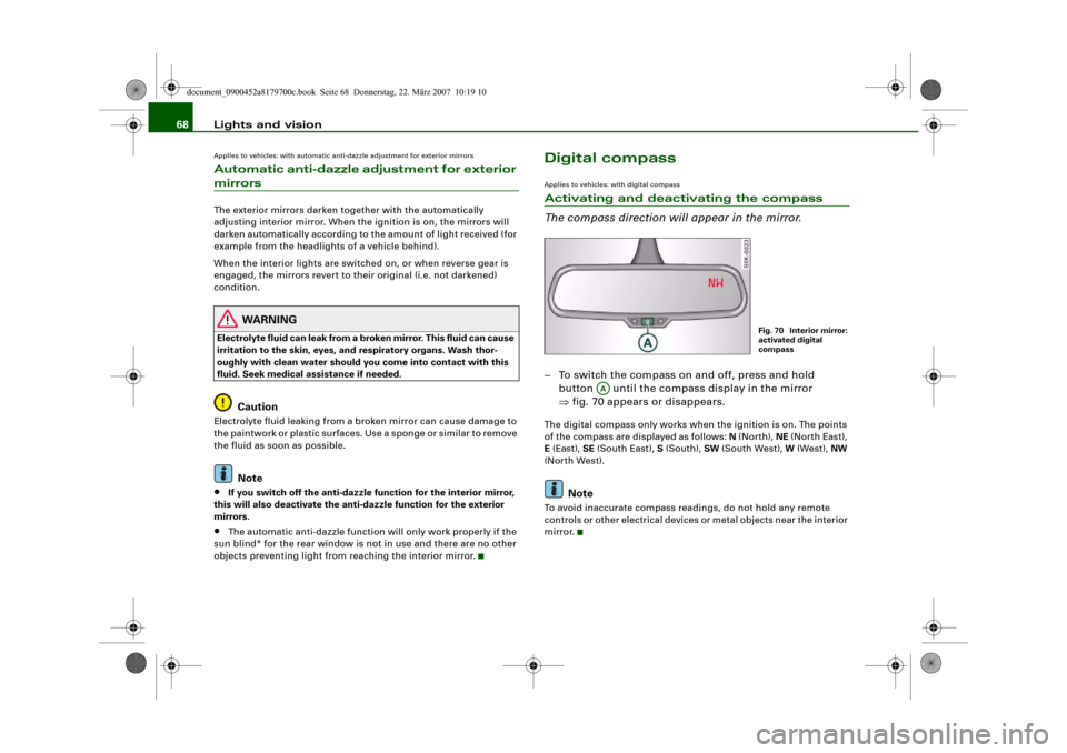
The compass direction will appear in the mirror.– To switch the compass on and off, press and hold
button until the compass display in the mirror
⇒fig. 70 appears or disappears.The digital compass only works when the ignition is on. The points
of the compass are displayed as follows: N (North), NE (North East),
E (East), SE (South East), S (South), SW (South West), W (West), NW
(North West).
Note
To avoid inaccurate compass readings, do not hold any remote
controls or other electrical devices or metal objects near the interior
mirror.
Fig. 70 Interior mirror:
activated digital
compass
AA
document_0900452a8179700c.book Seite 68 Donnerstag, 22. März 2007 10:19 10
Page 84 of 313
Seats and storage 82
WARNING
The rear backrest must always be securely latched so that objects
stored in the luggage compartment will not fly forward during
sudden braking.
Caution
When returning the backrest to an upright position, make sure that
the seat belts for the rear seats are in their guides so that they
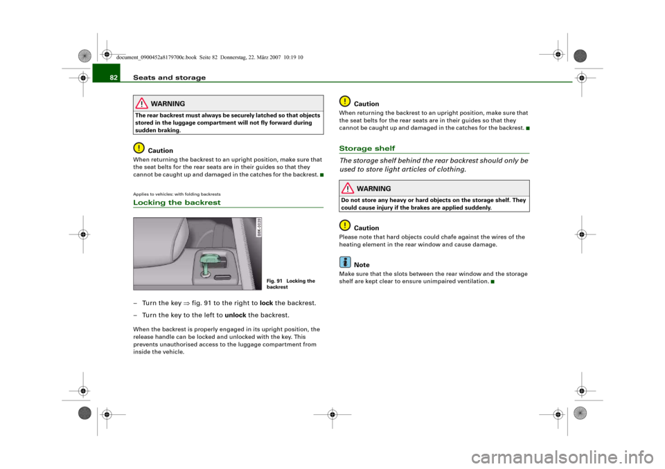
cannot be caught up and damaged in the catches for the backrest.Applies to vehicles: with folding backrestsLocking the backrest–Turn the key ⇒fig. 91 to the right to lock the backrest.
– Turn the key to the left to unlock the backrest.When the backrest is properly engaged in its upright position, the
release handle can be locked and unlocked with the key. This
prevents unauthorised access to the luggage compartment from
inside the vehicle.
Caution
When returning the backrest to an upright position, make sure that
the seat belts for the rear seats are in their guides so that they
cannot be caught up and damaged in the catches for the backrest.Storage shelf
The storage shelf behind the rear backrest should only be
used to store light articles of clothing.
WARNING
Do not store any heavy or hard objects on the storage shelf. They
could cause injury if the brakes are applied suddenly.
Caution
Please note that hard objects could chafe against the wires of the
heating element in the rear window and cause damage.
Note
Make sure that the slots between the rear window and the storage
shelf are kept clear to ensure unimpaired ventilation.
Fig. 91 Locking the
backrest
document_0900452a8179700c.book Seite 82 Donnerstag, 22. März 2007 10:19 10
Page 86 of 313
Seats and storage 84
Securing the bag in the luggage compartment
– Two belts with hooks are attached to the bottom side of
the bag. Engage the hooks into the rear fastening rings
in the luggage compartment ⇒page 83, fig. 93.
Securing the objects in the bag
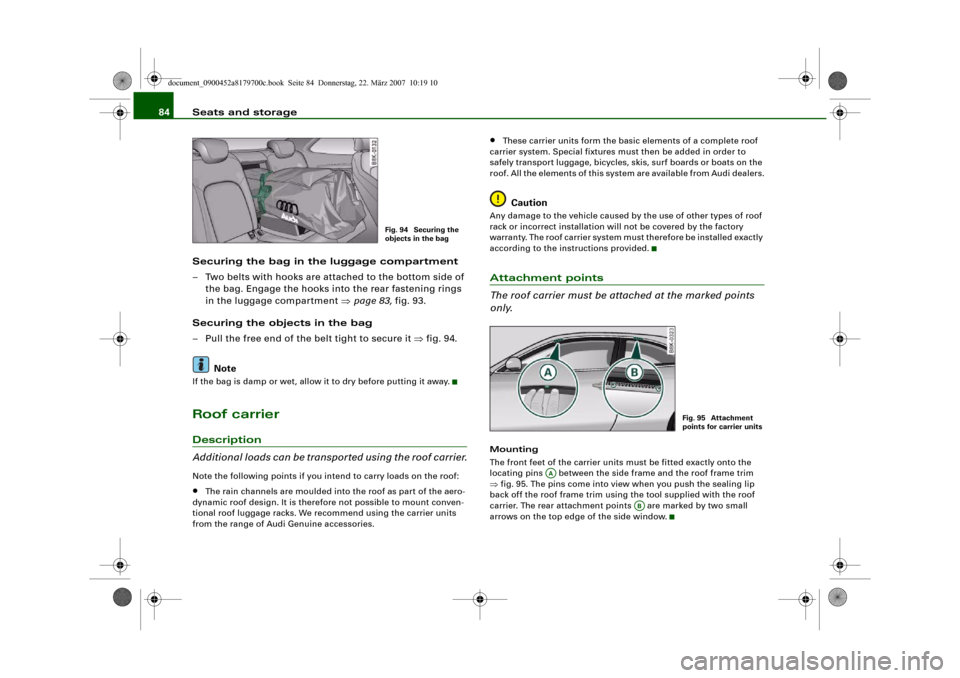
– Pull the free end of the belt tight to secure it ⇒fig. 94.
NoteIf the bag is damp or wet, allow it to dry before putting it away.Roof carrierDescription
Additional loads can be transported using the roof carrier.Note the following points if you intend to carry loads on the roof:•
The rain channels are moulded into the roof as part of the aero-
dynamic roof design. It is therefore not possible to mount conven-
tional roof luggage racks. We recommend using the carrier units
from the range of Audi Genuine accessories.
•
These carrier units form the basic elements of a complete roof
carrier system. Special fixtures must then be added in order to
safely transport luggage, bicycles, skis, surf boards or boats on the
roof. All the elements of this system are available from Audi dealers.Caution
Any damage to the vehicle caused by the use of other types of roof
rack or incorrect installation will not be covered by the factory
warranty. The roof carrier system must therefore be installed exactly
according to the instructions provided.Attachment points
The roof carrier must be attached at the marked points
only.Mounting
The front feet of the carrier units must be fitted exactly onto the
locating pins between the side frame and the roof frame trim
⇒fig. 95. The pins come into view when you push the sealing lip
back off the roof frame trim using the tool supplied with the roof
carrier. The rear attachment points are marked by two small
arrows on the top edge of the side window.
Fig. 94 Securing the
objects in the bag
Fig. 95 Attachment
points for carrier units
AA
AB
document_0900452a8179700c.book Seite 84 Donnerstag, 22. März 2007 10:19 10