Page 283 of 313
Fuses and bulbs281
Controls
Safety
Driving tips
General maintenance
Self-help
Technical data
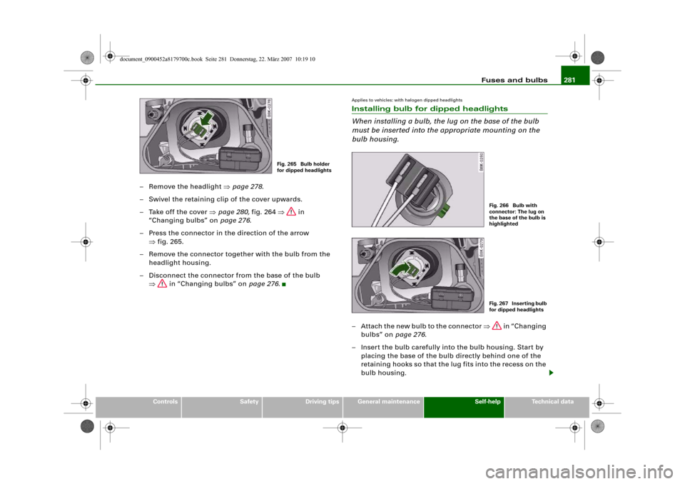
– Remove the headlight ⇒page 278.
– Swivel the retaining clip of the cover upwards.
– Take off the cover ⇒page 280, fig. 264 ⇒ in
“Changing bulbs” on page 276.
– Press the connector in the direction of the arrow
⇒fig. 265.
– Remove the connector together with the bulb from the
headlight housing.
– Disconnect the connector from the base of the bulb
⇒ in “Changing bulbs” on page 276.
Applies to vehicles: with halogen dipped headlightsInstalling bulb for dipped headlights
When installing a bulb, the lug on the base of the bulb
must be inserted into the appropriate mounting on the
bulb housing.– Attach the new bulb to the connector ⇒ in “Changing
bulbs” on page 276.
– Insert the bulb carefully into the bulb housing. Start by
placing the base of the bulb directly behind one of the
retaining hooks so that the lug fits into the recess on the
bulb housing.
Fig. 265 Bulb holder
for dipped headlights
Fig. 266 Bulb with
connector: The lug on
the base of the bulb is
highlightedFig. 267 Inserting bulb
for dipped headlights
document_0900452a8179700c.book Seite 281 Donnerstag, 22. März 2007 10:19 10
Page 285 of 313
Fuses and bulbs283
Controls
Safety
Driving tips
General maintenance
Self-help
Technical data
– Use a clean cloth to remove any fingerprints from the
glass part of the bulb.
– Insert the bulb carrier into the headlight.
– Fit the cover and swivel the retaining clip downwards.
– Install the headlight ⇒page 278.
– Check whether the new bulb is working.Changing bulb for front fog lightsPreparations
The description for changing the bulb refers to the left fog
light; in principle the same procedure applies to the right
fog light.
– Switch off the ignition and the lights.
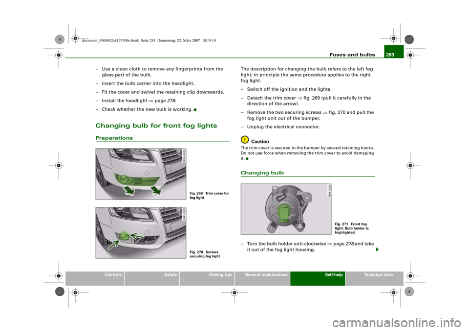
– Detach the trim cover ⇒fig. 269 (pull it carefully in the
direction of the arrow).
– Remove the two securing screws ⇒fig. 270 and pull the
fog light unit out of the bumper.
– Unplug the electrical connector.
CautionThe trim cover is secured to the bumper by several retaining hooks.
Do not use force when removing the trim cover to avoid damaging
it.Changing bulb– Turn the bulb holder anti-clockwise ⇒page 278 and take
it out of the fog light housing.
Fig. 269 Trim cover for
fog lightFig. 270 Screws
securing fog light
Fig. 271 Front fog
light: Bulb holder is
highlighted
document_0900452a8179700c.book Seite 283 Donnerstag, 22. März 2007 10:19 10
Page 287 of 313
Fuses and bulbs285
Controls
Safety
Driving tips
General maintenance
Self-help
Technical data
– Turn the screwdriver anti-clockwise to loosen the screw
and then carefully remove the screw.
– Gradually ease the light housing out of the rubber
mountings (positions ⇒page 284, fig. 274 and ) by
pulling alternately in direction of arrows and . If
necessary use the tool for changing bulbs from your
vehicle's toolkit to carefully apply some pressure
between positions and ⇒.
– Unplug the electrical connector.
– Change the defective bulb ⇒page 285.
CautionWhen removing or installing the rear light, take care not to cause
any damage.•
Removing the rear light in particular can lead to the paintwork or
rear light becoming damaged. This is another reason why we
recommend having the bulbs changed by a qualified workshop.
•
NEVER use metal tools (e.g. a screwdriver) or sharp or pointed
plastic tools to lever out the rear light - risk of damaging the paint.Note
Make sure you have a soft cloth ready to place under the glass on
the rear light, to avoid any scratches.
Changing bulbs
All bulbs can be changed easily after removing the rear
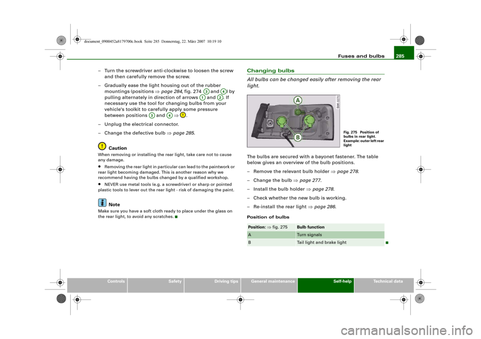
light.The bulbs are secured with a bayonet fastener. The table
below gives an overview of the bulb positions.
– Remove the relevant bulb holder ⇒page 278.
–Change the bulb ⇒page 277.
– Install the bulb holder ⇒page 278.
– Check whether the new bulb is working.
– Re-install the rear light ⇒page 286.Position of bulbs
A3
A4
A1
A2
A3
A4
Position: ⇒fig. 275
Bulb function
A
Turn signals
B
Tail light and brake light
Fig. 275 Position of
bulbs in rear light.
Example: outer left rear
light
document_0900452a8179700c.book Seite 285 Donnerstag, 22. März 2007 10:19 10
Page 289 of 313
Fuses and bulbs287
Controls
Safety
Driving tips
General maintenance
Self-help
Technical data
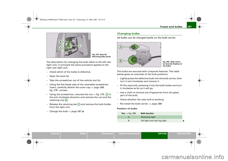
The description for changing the bulb refers to the left rear
light unit; in principle the same procedure applies to the
right rear light unit.
– Check which of the bulbs is defective.
– Open the boot lid.
– Take the screwdriver out of the vehicle tool kit.
– Using the flat-blade side of the reversible screwdriver
insert, carefully detach the cover cap ⇒page 286,
fig. 278 -arrows-.
– Using the screwdriver, unscrew the nut ⇒fig. 279 in
the anti-clockwise direction and remove the nut and the
retaining clip .
– Release the retaining tab and remove the bulb holder
from the light unit.
– Change the bulb ⇒page 287.
Changing bulbs
All bulbs can be changed easily on the bulb carrier.The bulbs are secured with a bayonet fastener. The table
below gives an overview of the bulb positions.
– Lightly press the defective bulb into the bulb carrier, then
turn it anti-clockwise and remove it.
– Fit the new bulb, pressing it into the bulb holder and turn
it clockwise as far as it will go.
– Use a cloth to remove any fingerprints from the glass
part of the bulb.
– Check whether the new bulb is working.
– Re-install the bulb carrier ⇒page 288.Position of bulbs
Fig. 279 Boot lid:
Removing bulb carrier
AA
AB
AC
Pos. ⇒fig. 280
Bulb function
A
Reversing light
B
Tail light and rear fog light
Fig. 280 Bulb carrier
for boot lid: Position of
the bulbs
document_0900452a8179700c.book Seite 287 Donnerstag, 22. März 2007 10:19 10
Page 291 of 313
Fuses and bulbs289
Controls
Safety
Driving tips
General maintenance
Self-help
Technical data
Changing bulb
– Press the defective bulb out of the bulb holder and fit the
new bulb.
Installing number plate light
– First insert the side with the retaining element
⇒page 288, fig. 283 and then carefully press the number
plate light into the opening.
– Check whether the new bulb is working.
document_0900452a8179700c.book Seite 289 Donnerstag, 22. März 2007 10:19 10
Page 295 of 313
General notes293
Controls
Safety
Driving tips
General maintenance
Self-help
Technical data This applies especially when the vehicle is fully laden.
CapacitiesFuel tank
Windscreen washerVehicle identification data
Vehicle identification number on the sound
system or MMI
– Select: Function selector button > Vehicle ID
number ⇒fig. 284.Vehicle identification number in the engine
compartment
The vehicle identification number is located on the right-hand side
of the engine compartment.
Type plate
The type plate is located on the right-hand side of the engine
compartment. Vehicles for certain export countries have no type
plate.
Front-wheel drive
ltr.
approx. 64
Four-wheel drive
ltr.
approx. 65
Windscreen and
headlight washer system*
ltr.
approx. 4.5
Fig. 284 MMI display:
Vehicle identification
number
Fig. 285 Vehicle data
sticker
CAR
document_0900452a8179700c.book Seite 293 Donnerstag, 22. März 2007 10:19 10
Page 297 of 313
Performance, weights and dimensions295
Controls
Safety
Driving tips
General maintenance
Self-help
Technical data
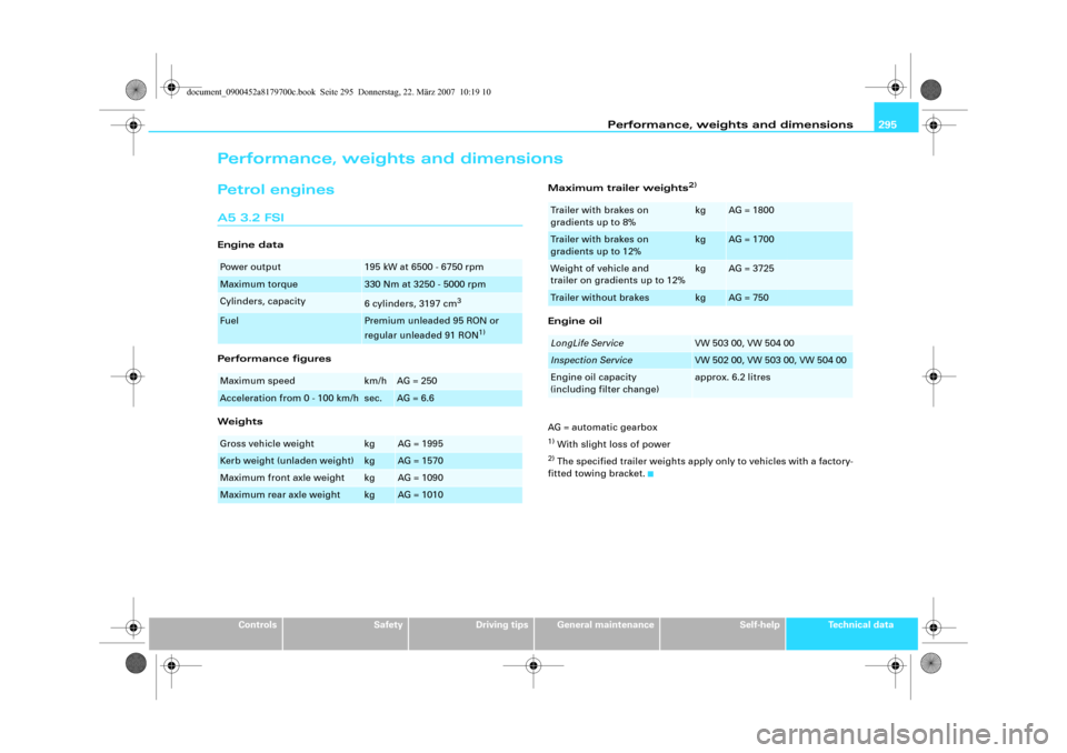
Performance, weights and dimensionsPetrol enginesA5 3.2 FSIEngine data
Performance figures
WeightsMaximum trailer weights
2)
Engine oil
AG = automatic gearbox1) With slight loss of power2) The specified trailer weights apply only to vehicles with a factory-
fitted towing bracket.
Power output
195 kW at 6500 - 6750 rpm
Maximum torque
330 Nm at 3250 - 5000 rpm
Cylinders, capacity
6 cylinders, 3197 cm
3
Fuel
Premium unleaded 95 RON or
regular unleaded 91 RON
1)
Maximum speed
km/h
AG = 250
Acceleration from 0 - 100 km/h
sec.
AG = 6.6
Gross vehicle weight
kg
AG = 1995
Kerb weight (unladen weight)
kg
AG = 1570
Maximum front axle weight
kg
AG = 1090
Maximum rear axle weight
kg
AG = 1010
Trailer with brakes on
gradients up to 8%
kg
AG = 1800
Trailer with brakes on
gradients up to 12%
kg
AG = 1700
Weight of vehicle and
trailer on gradients up to 12%
kg
AG = 3725
Trailer without brakes
kg
AG = 750
LongLife Service
VW 503 00, VW 504 00
Inspection Service
VW 502 00, VW 503 00, VW 504 00
Engine oil capacity
(including filter change)
approx. 6.2 litres
document_0900452a8179700c.book Seite 295 Donnerstag, 22. März 2007 10:19 10
Page 299 of 313
Performance, weights and dimensions297
Controls
Safety
Driving tips
General maintenance
Self-help
Technical data
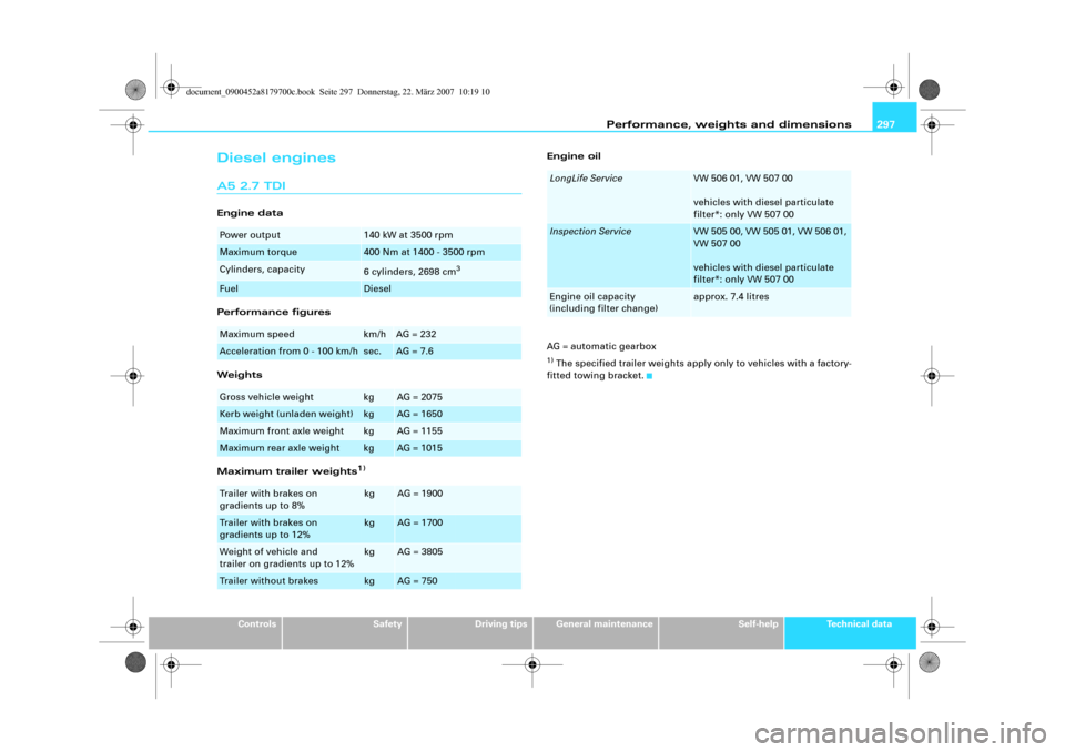
Diesel enginesA5 2.7 TDIEngine data
Performance figures
Weights
Maximum trailer weights
1)
Engine oil
AG = automatic gearbox1) The specified trailer weights apply only to vehicles with a factory-
fitted towing bracket.
Power output
140 kW at 3500 rpm
Maximum torque
400 Nm at 1400 - 3500 rpm
Cylinders, capacity
6 cylinders, 2698 cm
3
Fuel
Diesel
Maximum speed
km/h
AG = 232
Acceleration from 0 - 100 km/h
sec.
AG = 7.6
Gross vehicle weight
kg
AG = 2075
Kerb weight (unladen weight)
kg
AG = 1650
Maximum front axle weight
kg
AG = 1155
Maximum rear axle weight
kg
AG = 1015
Trailer with brakes on
gradients up to 8%
kg
AG = 1900
Trailer with brakes on
gradients up to 12%
kg
AG = 1700
Weight of vehicle and
trailer on gradients up to 12%
kg
AG = 3805
Trailer without brakes
kg
AG = 750
LongLife Service
VW 506 01, VW 507 00
vehicles with diesel particulate
filter*: only VW 507 00
Inspection Service
VW 505 00, VW 505 01, VW 506 01,
VW 507 00
vehicles with diesel particulate
filter*: only VW 507 00
Engine oil capacity
(including filter change)
approx. 7.4 litres
document_0900452a8179700c.book Seite 297 Donnerstag, 22. März 2007 10:19 10