2008 AUDI A4 clock setting
[x] Cancel search: clock settingPage 15 of 342
Instruments and warning/indicator lamps13
Controls
Safety
Driving tips
General maintenance
Self-help
Technical data The button has the following functions:
Activating clock, date, temperature and mileage
recorder displays
The display will appear for about 30 seconds if you press the
button ⇒page 12, fig. 3 when the ignition is switched off.
Starting check procedure (auto-check control)
The auto-check control checks important components and vehicle
systems. These background checks are run constantly, as long as
the ignition is switched on ⇒page 30.
You can start the “check procedure” manually by pressing the
button with the ignition switched on. This function check can be
started at road speeds up to 5 km/h.
Calling up driver messages again
A red or yellow symbol appearing in the instrument cluster display
is normally accompanied by a corresponding message. The
message will disappear from the display after about 5 seconds. If
required, you can call up the message again by briefly pressing the
button.
Setting speed warning
You can press the button briefly to set speed limit warning 1
while the vehicle is moving ⇒page 29. If you press and hold the
button, this will cancel the speed warning.
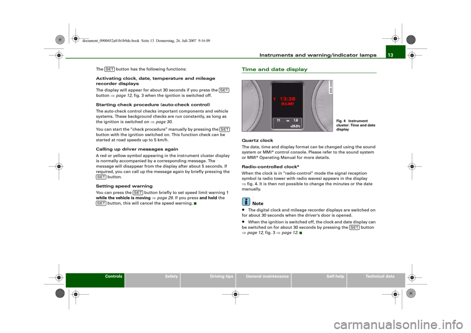
Time and date displayQuart z clock
The date, time and display format can be changed using the sound
system or MMI* control console. Please refer to the sound system
or MMI* Operating Manual for more details.
Radio-controlled clock*
When the clock is in “radio-control” mode the signal reception
symbol (a radio tower with radio waves) appears in the display
⇒fig. 4. It is then not possible to change the minutes or the date
manually.
Note
•
The digital clock and mileage recorder displays are switched on
for about 30 seconds when the driver's door is opened.
•
When the ignition is switched off, the clock and date display can
be switched on for about 30 seconds by pressing the button
⇒page 12, fig. 3 ⇒page 12.
SET
SETSET
SET
SET
SET
Fig. 4 Instrument
cluster: Time and date
display
SET
document_0900452a81b1b9de.book Seite 13 Donnerstag, 26. Juli 2007 9:16 09
Page 62 of 342
Lights and vision 60
– Turn the button clockwise +” to increase the brightness
of the instrument lighting in dark conditions.
– Turn the button anti-clockwise -” to reduce the bright-
ness of the instrument lighting in dark conditions.
– Press the knob in again to prevent the setting from being
changed unintentionally.The instrument lighting (dials and needles), the centre console illu-
mination and the illumination of the displays are regulated by a
light sensor incorporated in the instrument cluster. In bright condi-
tions any changes made to the brightness of the instrument lighting
have no effect.
Note
The instrument lighting (illumination of dials and needles) is
switched on when the ignition is on and the vehicle's lights are off.
The instrument lighting is dimmed automatically as the daylight
starts to fade; it is switched off completely when the light condi-
tions become very poor. This function is intended to remind the
driver to switch on the dipped-beam headlights in good time when
light conditions become poor.
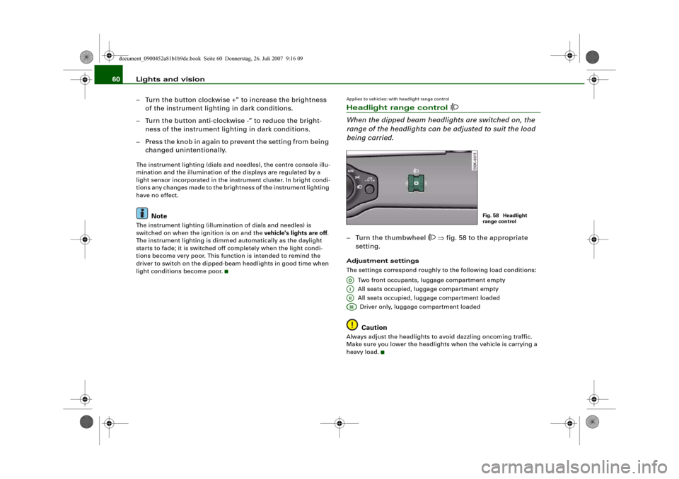
Applies to vehicles: with headlight range controlHeadlight range control
When the dipped beam headlights are switched on, the
range of the headlights can be adjusted to suit the load
being carried.– Turn the thumbwheel
⇒fig. 58 to the appropriate
setting.
Adjustment settings
The settings correspond roughly to the following load conditions:
Two front occupants, luggage compartment empty
All seats occupied, luggage compartment empty
All seats occupied, luggage compartment loaded
Driver only, luggage compartment loaded
Caution
Always adjust the headlights to avoid dazzling oncoming traffic.
Make sure you lower the headlights when the vehicle is carrying a
heavy load.
Fig. 58 Headlight
range control
AOAIAIIAIII
document_0900452a81b1b9de.book Seite 60 Donnerstag, 26. Juli 2007 9:16 09
Page 98 of 342
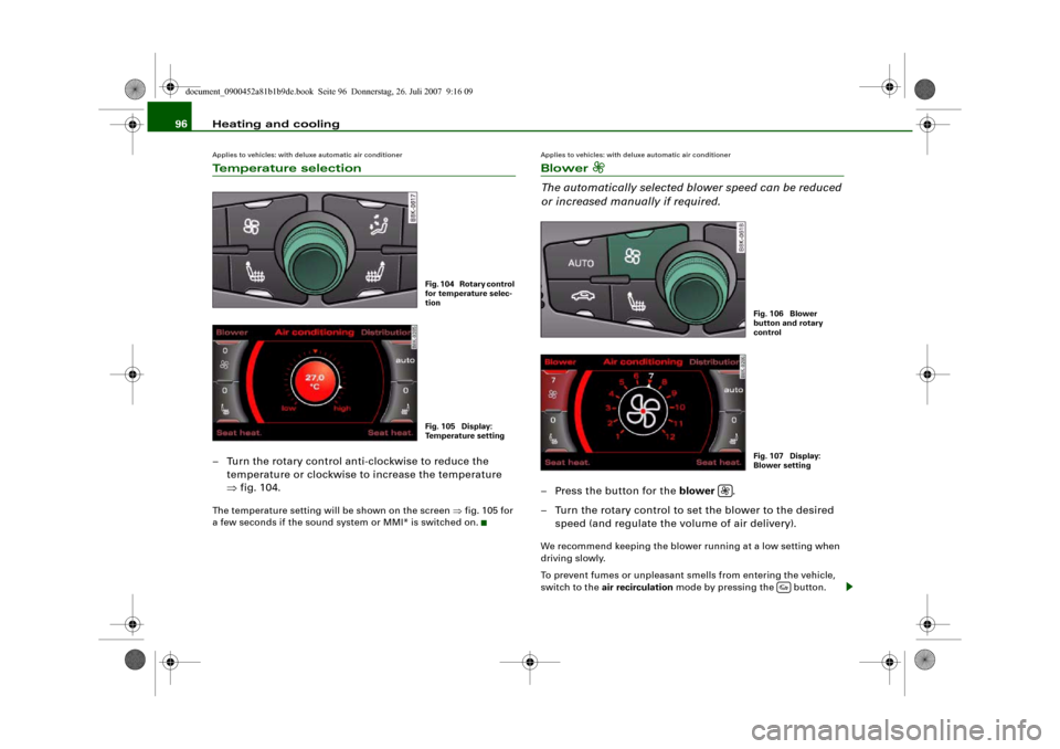
Heating and cooling 96Applies to vehicles: with deluxe automatic air conditionerTemperature selection– Turn the rotary control anti-clockwise to reduce the
temperature or clockwise to increase the temperature
⇒fig. 104.The temperature setting will be shown on the screen ⇒fig. 105 for
a few seconds if the sound system or MMI* is switched on.
Applies to vehicles: with deluxe automatic air conditionerBlower
The automatically selected blower speed can be reduced
or increased manually if required.– Press the button for the blower .
– Turn the rotary control to set the blower to the desired
speed (and regulate the volume of air delivery).We recommend keeping the blower running at a low setting when
driving slowly.
To prevent fumes or unpleasant smells from entering the vehicle,
switch to the air recirculation mode by pressing the button.
Fig. 104 Rotary control
for temperature selec-
tionFig. 105 Display:
Temperature setting
Fig. 106 Blower
button and rotary
controlFig. 107 Display:
Blower setting
document_0900452a81b1b9de.book Seite 96 Donnerstag, 26. Juli 2007 9:16 09
Page 106 of 342
Heating and cooling 104interior temperature as quickly as possible, and then to maintain
this temperature. The system automatically compensates for any
variations in the outside temperature and for the effect of direct
sunlight.
The automatic temperature regulation only operates at temperature
settings between +16 °C and +28 °C. If a temperature below +16 °C
is selected, LO appears on the display. If a temperature above +28 °C
is selected, the display will show HI. In the two extreme settings the
air conditioner operates continuously with maximum cooling or
heating output, and the temperature is not regulated
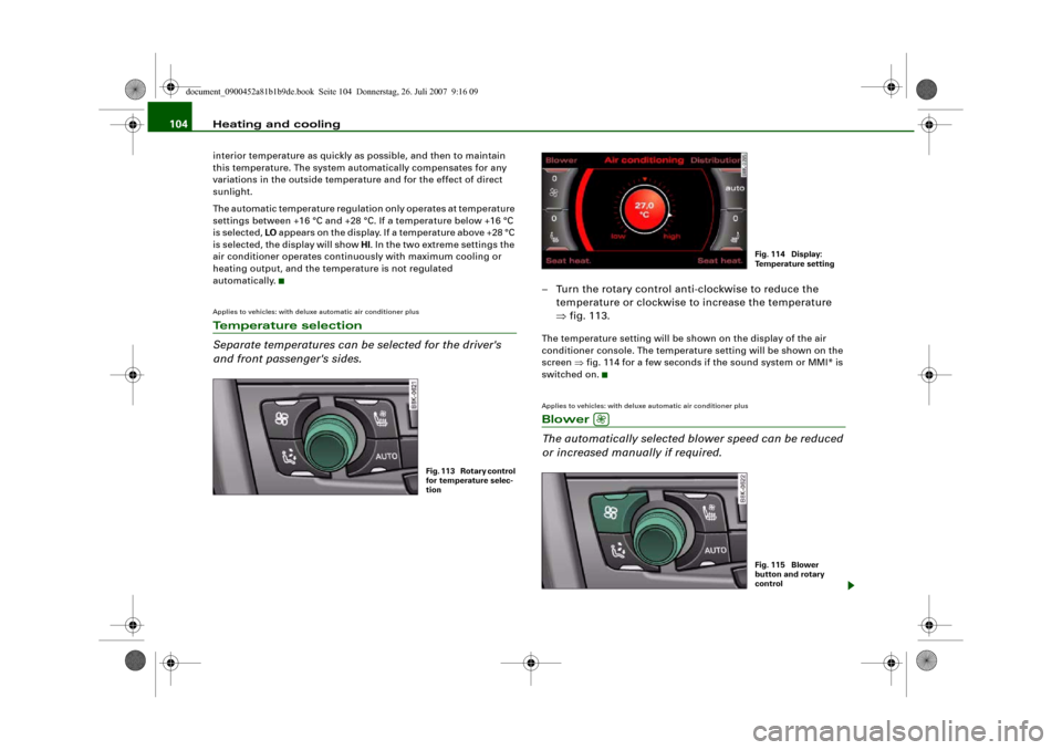
automatically.Applies to vehicles: with deluxe automatic air conditioner plusTemperature selection
Separate temperatures can be selected for the driver's
and front passenger's sides.
– Turn the rotary control anti-clockwise to reduce the
temperature or clockwise to increase the temperature
⇒fig. 113.The temperature setting will be shown on the display of the air
conditioner console. The temperature setting will be shown on the
screen ⇒fig. 114 for a few seconds if the sound system or MMI* is
switched on.Applies to vehicles: with deluxe automatic air conditioner plusBlower
The automatically selected blower speed can be reduced
or increased manually if required.
Fig. 113 Rotary control
for temperature selec-
tion
Fig. 114 Display:
Te m p e r a t u r e s e t t i n g
Fig. 115 Blower
button and rotary
control
document_0900452a81b1b9de.book Seite 104 Donnerstag, 26. Juli 2007 9:16 09
Page 113 of 342
Heating and cooling111
Controls
Safety
Driving tips
General maintenance
Self-help
Technical data
Note
•
It is advisable to open the air outlets when using the auxiliary
heating/ventilation.
•
The auxiliary heating/ventilation will not switch on if the fuel in
the tank has reached the reserve zone.
•
The auxiliary heating/ventilation will not switch on if the battery
charge level is low.
•
The symbols
(auxiliary ventilation) or
(auxiliary heating)
flash in the instrument cluster next to the clock display when the
auxiliary heating/ventilation is switched on. Both symbols light
continuously when the timer is activated.
•
At low outside temperatures some visible water vapour may
form in the engine compartment. This is a normal phenomenon,
and no reason for concern.
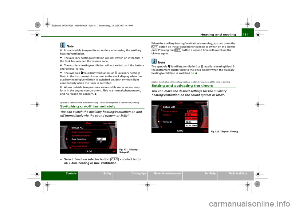
Applies to vehicles: with auxiliary heating - under development at the time of printingSwitching on/off immediately
You can switch the auxiliary heating/ventilation on and
off immediately via the sound system or MMI*.– Select: Function selector button > control button
AC > Aux. heating or Aux. ventilation.
When the auxiliary heating/ventilation is running, you can press the
button on the air conditioner console to switch off the blower
only. Pressing the button a second time will switch on the
blower again.
Note
The symbols
(auxiliary ventilation) or
(auxiliary heating) flash in
the instrument cluster next to the clock display when the auxiliary
heating/ventilation is switched on.
Applies to vehicles: with auxiliary heating - under development at the time of printingSetting and activating the timers
You can make the desired settings for the auxiliary
heating/ventilation on the sound system or MMI*.
Fig. 121 Display:
Setup AC
CAR
OFF
OFF
Fig. 122 Display: Timer
document_0900452a81b1b9de.book Seite 111 Donnerstag, 26. Juli 2007 9:16 09
Page 116 of 342
Heating and cooling 114Transmitting range
The range of the remote control transmitter is about 600 metres.
However, this can be greatly reduced by obstacles (buildings, etc.)
between the remote control transmitter and the vehicle. Hold the
aerial upright when using the remote control.
You should not normally use the remote control at a distance of less
than 3 metres from the vehicle. If you are closer than this, or if you
use the remote control inside the vehicle, this can cause signal over-
load.
For the sake of the environment
Please dispose of old batteries in the proper manner so that they do
not harm the environment.Seat heatingApplies to vehicles: with front seat heating/ventilationSeat heating / ventilation
The seat cushions and backrests of the front seats can be
heated and ventilated* electrically.
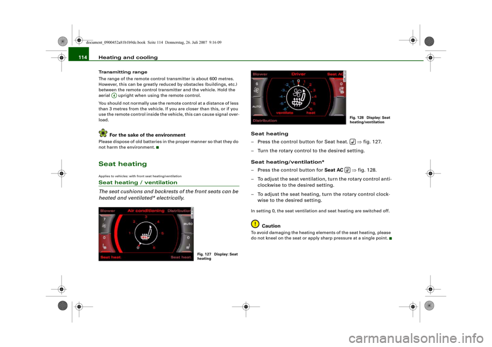
Seat heating
– Press the control button for Seat heat. ⇒fig. 127.
– Turn the rotary control to the desired setting.
Seat heating/ventilation*
– Press the control button for Seat AC ⇒fig. 128.
– To adjust the seat ventilation, turn the rotary control anti-
clockwise to the desired setting.
– To adjust the seat heating, turn the rotary control clock-
wise to the desired setting.In setting 0, the seat ventilation and seat heating are switched off.
Caution
To avoid damaging the heating elements of the seat heating, please
do not kneel on the seat or apply sharp pressure at a single point.
A4
Fig. 127 Display: Seat
heating
Fig. 128 Display: Seat
heating/ventilation
document_0900452a81b1b9de.book Seite 114 Donnerstag, 26. Juli 2007 9:16 09
Page 239 of 342
Towing a trailer237
Controls
Safety
Driving tips
General maintenance
Self-help
Technical data
– Also check the shaft section of the ball joint and its asso-
ciated mechanical parts to make sure they are clean and
undamaged.Continued ⇒page 237, “Fitting the ball joint (step 2)”.
WARNING
It is important to keep the mounting fixture clean. Otherwise the
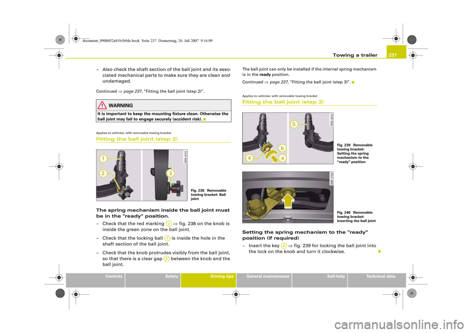
ball joint may fail to engage securely (accident risk).Applies to vehicles: with removable towing bracketFitting the ball joint (step 2)The spring mechanism inside the ball joint must
be in the "ready" position.
– Check that the red marking ⇒fig. 238 on the knob is
inside the green zone on the ball joint.
– Check that the locking ball is inside the hole in the
shaft section of the ball joint.
– Check that the knob protrudes visibly from the ball joint,
so that there is a clear gap between the knob and the
ball joint.
The ball joint can only be installed if the internal spring mechanism
is in the ready position.
Continued ⇒page 237, “Fitting the ball joint (step 3)”.Applies to vehicles: with removable towing bracketFitting the ball joint (step 3)Setting the spring mechanism to the "ready"
position (if required)
– Insert the key ⇒fig. 239 for locking the ball joint into
the lock on the knob and turn it clockwise.
Fig. 238 Removable
towing bracket: Ball
joint
A2A1A3
Fig. 239 Removable
towing bracket:
Setting the spring
mechanism to the
"ready" positionFig. 240 Removable
towing bracket:
Inserting the ball joint
A4
document_0900452a81b1b9de.book Seite 237 Donnerstag, 26. Juli 2007 9:16 09
Page 334 of 342
Index 332CCapacities . . . . . . . . . . . . . . . . . . . . . . . . . 321
Car keys . . . . . . . . . . . . . . . . . . . . . . . . . . . . 43
Care of vehicle . . . . . . . . . . . . . . . . . . . . . 244
Catalytic converter . . . . . . . . . . . . . . . . . . 229
Central locking system . . . . . . . . . . . . . . . 42
Boot lid . . . . . . . . . . . . . . . . . . . . . . . . . . 51
Deadlock mechanism . . . . . . . . . . . . . . 48
Fuel tank flap . . . . . . . . . . . . . . . . . . . . 252
Locking . . . . . . . . . . . . . . . . . . . . . . . . . . 48
Locking and unlocking the vehicle from
inside . . . . . . . . . . . . . . . . . . . . . . . . . . 49
Manual locking . . . . . . . . . . . . . . . . . . . 51
Opening and closing windows . . . . . . 54
Sun roof . . . . . . . . . . . . . . . . . . . . . . . . . 54
Switches on driver's door . . . . . . . . . . 49
Unlocking . . . . . . . . . . . . . . . . . . . . . . . . 48
Cetane number . . . . . . . . . . . . . . . . . . . . . 251
Changing a wheel . . . . . . . . . . . . . . . . . . . 288
Changing bulbs
SeeBulbs . . . . . . . . . . . . . . . . . . . . . . . 304
Chassis number . . . . . . . . . . . . . . . . . . . . 321
Child safety . . . . . . . . . . . . . . . . . . . . . . . . 210
Side airbags . . . . . . . . . . . . . . . . . . . . . 212
Child safety seat . . . . . . . . . . . . . . . . . . . . 213
Child seat categories . . . . . . . . . . . . . 213
Fitting . . . . . . . . . . . . . . . . . . . . . . . . . . 216
ISOFIX system . . . . . . . . . . . . . . . . . . . 218
On front passenger's seat . . . . . . . . . 211
Safety notes . . . . . . . . . . . . . . . . . . . . . 210
Child-proof catches
Rear doors . . . . . . . . . . . . . . . . . . . . . . . 53Cigarette lighter . . . . . . . . . . . . . . . . . . . . . 87
Cleaning . . . . . . . . . . . . . . . . . . . . . . . . . . . 244
Cleaning Alcantara . . . . . . . . . . . . . . . . . . 250
Cleaning seat covers
Alcantara . . . . . . . . . . . . . . . . . . . . . . . 250
Natural leather . . . . . . . . . . . . . . . . . . 249
Textile covers . . . . . . . . . . . . . . . . . . . . 247
Cleaning textile covers and trim parts . . 247
Clock, setting . . . . . . . . . . . . . . . . . . . . . . . 13
Closing
Bonnet . . . . . . . . . . . . . . . . . . . . . . . . . 256
Sun roof . . . . . . . . . . . . . . . . . . . . . . . . . 55
Coat hooks . . . . . . . . . . . . . . . . . . . . . . . . . . 91
Colour code . . . . . . . . . . . . . . . . . . . . . . . . 321
coming home . . . . . . . . . . . . . . . . . . . . . . . 59
Compact temporary spare wheel
SeeSpare wheel . . . . . . . . . . . . . . . . . 284
Compartment for (sun)glasses . . . . . . . . . 91
Compass in mirror . . . . . . . . . . . . . . . . . . . 71
Controls and displays
Overview . . . . . . . . . . . . . . . . . . . . . . . . . . 9
Convenience open/close function . . . . . . 54
Cooling system
Anti-freeze additive . . . . . . . . . . . . . . . 260
Checking coolant level . . . . . . . . . . . . 261
Coolant . . . . . . . . . . . . . . . . . . . . . . . . . 260
Coolant temperature gauge . . . . . . . . . 11
Malfunction . . . . . . . . . . . . . . . . . . . . . . 33
Radiator fan . . . . . . . . . . . . . . . . . . . . . 262
Topping up coolant . . . . . . . . . . . . . . . 261Cruise control system
Adjusting stored speed . . . . . . . . . . . 126
Indicator lamp . . . . . . . . . . . . . . . . . . . . 19
Pre-selecting a speed . . . . . . . . . . . . . 127
Switching off . . . . . . . . . . . . . . . . . . . . 127
Switching on . . . . . . . . . . . . . . . . . . . . 125
See alsoadaptive cruise control . . . . 128
Cup holders . . . . . . . . . . . . . . . . . . . . . . . . . 85
Current fuel consumption . . . . . . . . . . . . . 25
DDate display . . . . . . . . . . . . . . . . . . . . . . . . . 13
Daytime running lights . . . . . . . . . . . . . . . 59
DCP
SeeDynamic gear control program . 166
Deactivating front passenger's airbag . . 208
Deadlock mechanism . . . . . . . . . . . . . . 42, 48
Defrosting windows . . . . . . . . . . . . . . 98, 106
Deluxe automatic air conditioner . . . . . . . 93
Air distribution . . . . . . . . . . . . . . . . . . . 97
Air outlets . . . . . . . . . . . . . . . . . . . . . . . . 99
Air outlets for rear passengers . . . . . . 99
Air recirculation mode . . . . . . . . . . . . . 97
Automatic mode . . . . . . . . . . . . . . . . . . 95
Basic settings . . . . . . . . . . . . . . . . . . . . 100
Blower . . . . . . . . . . . . . . . . . . . . . . . . . . . 96
Controls . . . . . . . . . . . . . . . . . . . . . . . . . 94
Defrosting . . . . . . . . . . . . . . . . . . . . . . . 98
Description . . . . . . . . . . . . . . . . . . . . . . . 93
Economical operation . . . . . . . . . . . . . 100
Heated rear window . . . . . . . . . . . . . . . 98
Seat heating, front . . . . . . . . . . . . . . . 114
document_0900452a81b1b9de.book Seite 332 Donnerstag, 26. Juli 2007 9:16 09