2008 AUDI A4 Plug
[x] Cancel search: PlugPage 159 of 342
Audi side assist157
Controls
Safety
Driving tips
General maintenance
Self-help
Technical data Audi side assist: system fault
The system should be checked by an Audi dealership or other qual-
ified workshop.
Audi side assist not available when towing
On vehicles with a factory-fitted towing bracket the side assist func-
tion will be switched off automatically when the electrical connector
for the trailer is plugged in, and this message will appear in the
instrument cluster display. The side assist function may not be
switched off automatically if the towing bracket is not of the factory-
fitted type.
Applies to vehicles: with side assistSafety notesThe function of the side assist can be restricted when driving in
tight bends or over crests and in bad weather conditions.
It is possible that the radar sensors may register objects such as
high or offset roadside barriers as well as other vehicles.
The side assist system is programmed for lanes of a fixed width, and
is not able to measure differing lane widths. It monitors a zone
equivalent to one normal lane width on either side. If the lanes are
narrower than this, or if vehicles are not travelling in the centre of
the lanes, the system may give a warning for vehicles which it
judges to be critical, even though they are not in fact travelling in an
adjacent lane.
WARNING
•
Please note that the sensors are not always able to detect all
vehicles which may represent a potential hazard (accident risk).
•
Please note that the side assist is not able to give adequate
warning of vehicles approaching very fast from behind, or vehicles
that you are overtaking rapidly.
•
The radar sensor's "field of vision" can be impaired by rain,
snow or a lot of water on the road. This results in vehicles not
being reliably recognised or, in some circumstances, not being
detected at all by the side assist. Always give your full attention to
the position of your vehicle on the road and other nearby traffic.
•
The side assist only gives a warning of approaching vehicles
and vehicles in the blind spots when road speed is above 60 km/h.
•
Please note that the side assist does not operate in tight bends
(with a radius of less than 200 metres).
•
The side assist feature is not a substitute for the full concentra-
tion of the driver. The driver is always responsible for the safety of
lane changes and other manoeuvres. Always give your full atten-
tion to the position of your vehicle on the road and other nearby
traffic.Caution
To avoid impairing the function of the side assist, do not attach any
objects (e.g. stickers or bicycle carriers) in such a way that they
might interfere with the radar sensors in the rear bumper.
Note
For reasons of safety, the side assist system must be checked by a
qualified workshop if the positions of the radar sensors have been
affected by a rear-end collision, etc.Applies to vehicles: with side assistConformity certificationThe side assist employs radar sensors operating in one of two
frequency bands at 24 GHz. Please note that in some countries only
one of these two frequency bands is permitted. Accordingly, the
frequency band permitted in the country where the vehicle is being
WARNING (continued)
document_0900452a81b1b9de.book Seite 157 Donnerstag, 26. Juli 2007 9:16 09
Page 234 of 342
Towing a trailer 232Towing a trailerDriving the vehicle with a trailer or
caravanTechnical requirements
The towing bracket must comply with certain technical
requirements.Your car is intended mainly for transporting passengers and
luggage. However, if suitably equipped, it can also be used to tow a
trailer or caravan.
If the car is supplied with a factory-fitted towing bracket it will
already have the necessary technical modifications and meet the
statutory requirements.
A 13-pin socket is provided to make the electrical connection
between the car and the trailer. If the trailer has a 7-pin plug you can
use an adapter cable. This is available from Audi dealers.
WARNING
If a towing bracket is retrofitted, the installation should be carried
out by a qualified workshop.•
In particular in high outside temperatures it is not possible to
drive up long steep gradients without a suitable cooling system.
The engine would then overheat.
•
Incorrect installation can result in a safety risk.
Points to check before towingTrailer weights
Never exceed the maximum permitted trailer weights ⇒page 323.If you do not load the trailer up to the maximum permitted trailer
weight, you can then climb correspondingly steeper gradients.
The maximum trailer weights listed are only applicable for altitudes
up to 1000 m above sea level. With increasing altitude the engine
power and therefore the car's climbing ability are impaired because
of the reduced air density, so the maximum trailer weight has to be
reduced accordingly. The weight of the car and trailer must be
reduced by 10% for every further 1000 m (or part thereof). This
figure refers to the combined weight of the (loaded) vehicle and
(loaded) trailer.
The figures for the draw bar weight that appear on the identification
plate of the towing bracket are for certification purposes only. The
correct figures for your specific vehicle, which may be lower than
these figures for the towing bracket, are given in the registration
documents. Also refer to ⇒page 323.
Distributing the load
Distribute loads in the trailer so that heavy objects are as near to the
axle as possible. Loads carried in the trailer must be secured to
prevent them slipping.
Where possible, operate the trailer with the maximum permitted
draw bar weight on the ball joint of the towing bracket, but do not
exceed the specified limit.
Tyre pressure
Check the tyre pressures on your car and adjust for “full load” condi-
tions (refer to the sticker listing the tyre pressures on the end face
of the driver's door). It may also be necessary to adjust the tyre pres-
sures on the trailer according to the recommendations of the trailer
manufacturer.
Exterior mirrors
Check whether you can see enough of the road behind the trailer
with the standard mirrors. If this is not the case you should have
document_0900452a81b1b9de.book Seite 232 Donnerstag, 26. Juli 2007 9:16 09
Page 289 of 342

Self-help287
Controls
Safety
Driving tips
General maintenance
Self-help
Technical data
– Check whether a repair is possible using the Tyre
Mobility System ⇒page 285.
– Ensure that all passengers leave the vehicle and move
away from the danger area ⇒.
– Take the tyre sealant can and the electric compressor out
of the luggage compartment ⇒page 283.
– Fix the sticker “max. 80 km/h”, which is included with the
tyre sealant can, onto the instrument cluster where the
driver will see it.
Filling the tyre
– Shake the tyre sealant can well.
– Screw the enclosed filling hose onto the sealant can as
far as it will go. This will automatically pierce the foil
sealing the can.
– Take the valve cap off the tyre valve and use the enclosed
valve insert tool to unscrew the valve insert ⇒page 286,
fig. 270.
– Place the valve insert onto a clean surface.
– Remove the sealing plug from the filling hose and insert
the hose into the tyre valve.
– Hold the tyre sealant can upside down and fill the
complete contents of the can into the tyre.
– Then disconnect the hose and screw the valve insert
firmly back into the tyre valve.Inflating the tyre
– Screw the filling hose of the electric compressor onto the
tyre valve and plug the connector into the cigarette
lighter.
– Pump the tyre up to 2.0 to 2.5 bar and monitor the pres-
sure shown on the pressure gauge.
– If the tyre pressure remains lower than the value speci-
fied above drive the vehicle approx. 10 metres forwards
or backwards, so that the sealant can spread evenly in
the tyre. If the pressure is still lower than the specifica-
tion the tyre is too badly damaged and cannot be
repaired using the tyre sealant.
Final checks
– After about 10 minutes stop to check the tyre pressure.
– If tyre pressure is less than 1.3 bar, the tyre is too badly
damaged. Do not drive on. You should obtain profes-
sional assistance.
WARNING
•
If you have a puncture in moving traffic, switch on the hazard
warning lights and place the warning triangle in a visible location.
This is for your own safety and also warns other road users.
•
Make sure your passengers wait in a safe place (for instance
behind the roadside crash barrier).
•
Please observe the manufacturers' safety notes on the
compressor and the instructions supplied with the tyre sealant
can.
•
If it was not possible to build up a tyre pressure of 2.0 bar
within 6 minutes this means that the tyre is too badly damaged.
Do not drive on.
document_0900452a81b1b9de.book Seite 287 Donnerstag, 26. Juli 2007 9:16 09
Page 297 of 342
Self-help295
Controls
Safety
Driving tips
General maintenance
Self-help
Technical data terminal must not touch metal parts of the vehicle: this can cause
short circuiting.
•
Do not bend over the batteries – risk of acid burns.
•
The screw plugs on the battery cells must be screwed in firmly.
•
Keep sparks, flame and lighted cigarettes away from batteries:
the gases given off can cause an explosion.
•
If jump-starting another vehicle, position the jump leads in
such a way that they cannot come into contact with any moving
parts in the engine compartment of the other vehicle.Caution
Please note that the above method of connecting the leads is meant
for jump-starting your vehicle. If jump-starting another vehicle, you
should not connect the negative lead (–) to the negative terminal of
the discharged battery, but directly to the engine block or a solid
metal part bolted to the engine block. If the battery of the other
vehicle does not have a gas vent, there is a risk that a mixture of
oxygen and hydrogen gas can accumulate and cause an
explosion.Tow-starting and towing awayGeneral notes
Points to observe when tow-starting or towing awayIf you use a towrope:
Notes for the driver of the towing vehicle
– The towrope must be taut before driving off.– Engage the clutch very gently when starting to move; on
vehicles with automatic gearbox press the accelerator
slowly.
Notes for the driver of the towed vehicle
– The ignition should be switched on so that the turn
signals, horn, windscreen wipers and washers can be
used. Please ensure that the steering wheel is unlocked
when you switch on the ignition, and that it moves freely.
–Put gear lever in neutral (manual gearbox) or move
selector lever to position N (automatic gearbox).
– The brake servo and power steering only work when the
engine is running. Considerably more effort is required
on the brake pedal and steering wheel when the engine
is switched off.
– Ensure that the towrope remains taut at all times when
towing.
Towrope or towbar
It is easier and safer to tow a vehicle with a towbar. You should only
use a towrope if you do not have a towbar.
A towrope should be slightly elastic to reduce the loading on both
vehicles. It is advisable to use a towrope made of synthetic fibre or
similar material.
Attach the tow-rope or tow-bar only to the towing anchorages
intended for this purpose ⇒page 296 or ⇒page 297.
Driving technique
Towing requires some experience – especially when using a
towrope. Both drivers should be familiar with the technique required
for towing. Inexperienced drivers should not attempt to tow-start or
tow away another vehicle.
WARNING (continued)
document_0900452a81b1b9de.book Seite 295 Donnerstag, 26. Juli 2007 9:16 09
Page 309 of 342

Fuses and bulbs307
Controls
Safety
Driving tips
General maintenance
Self-help
Technical data
– Take the screwdriver and the interchangeable Torx socket
out of the vehicle tool kit.
– Remove the screws ⇒page 306, fig. 288 that secure the
trim panel to the lock carrier and detach the trim panel.
– Slacken the two screws that secure the headlight to the
lock carrier and the two screws at the underside of the
headlight (the screws at the underside should not be
slackened more than five turns) ⇒page 306, fig. 289.
– Carefully pull the headlight forward about 60 mm.
– Release and unplug the electrical connector.
– Carefully take the headlight out towards the front (swivel
it slightly if necessary).
Installing
– Perform all of the above steps in reverse sequence.The headlight must be inserted in two guides (on the underside of
the headlight). This is the only way to ensure that the headlight is
installed in the correct position. To determine whether the headlight
is correctly installed, check that it is aligned flush with adjacent
body parts (such as the wing panel).
Do not interchange the securing screws.
Caution
Please take particular care not to damage or scratch the adjacent
parts of the body when removing or installing the headlights.
Removing bulb for main beam headlights– Remove the headlight ⇒page 306.
– Take off the rubber cap ⇒fig. 290 ⇒ in “Changing
bulbs” on page 304.
– Press the connector in the direction of the arrow
⇒fig. 291.
– Remove the connector together with the bulb from the
headlight housing.
– Disconnect the connector from the base of the bulb
⇒ in “Changing bulbs” on page 304.
Fig. 290 Headlight
unit: Rubber cap is
highlightedFig. 291 Bulb holder
for main beam head-
lights
document_0900452a81b1b9de.book Seite 307 Donnerstag, 26. Juli 2007 9:16 09
Page 312 of 342
Fuses and bulbs 310
– Press the connector in the direction of the arrow
⇒page 309, fig. 297 until the bulb engages.
– Check that the bulb is securely seated in the bulb
housing.
–Fit the cover.
– Install the headlight ⇒page 306.
– Check whether the new bulb is working.
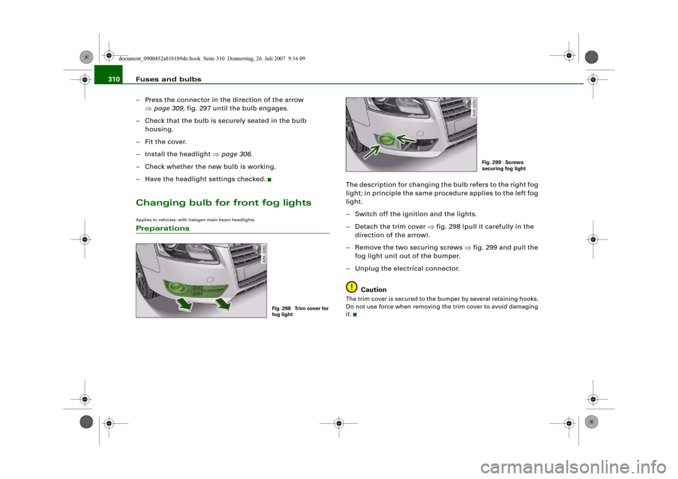
– Have the headlight settings checked.Changing bulb for front fog lightsApplies to vehicles: with halogen main beam headlightsPreparations
The description for changing the bulb refers to the right fog
light; in principle the same procedure applies to the left fog
light.
– Switch off the ignition and the lights.
– Detach the trim cover ⇒fig. 298 (pull it carefully in the
direction of the arrow).
– Remove the two securing screws ⇒fig. 299 and pull the
fog light unit out of the bumper.
– Unplug the electrical connector.
CautionThe trim cover is secured to the bumper by several retaining hooks.
Do not use force when removing the trim cover to avoid damaging
it.
Fig. 298 Trim cover for
fog light
Fig. 299 Screws
securing fog light
document_0900452a81b1b9de.book Seite 310 Donnerstag, 26. Juli 2007 9:16 09
Page 314 of 342
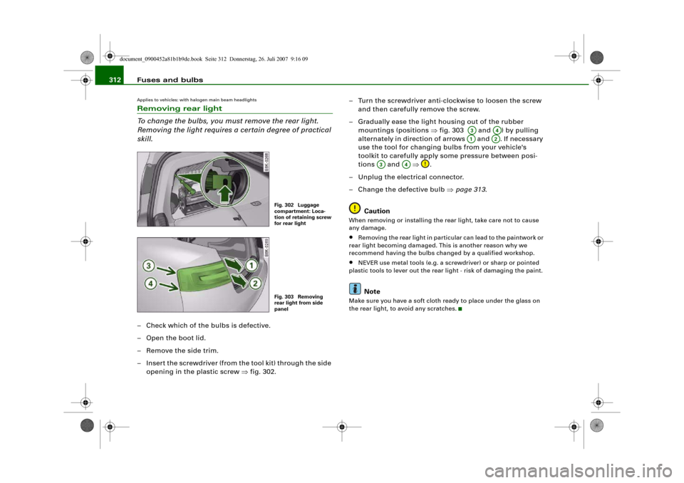
Fuses and bulbs 312Applies to vehicles: with halogen main beam headlightsRemoving rear light
To change the bulbs, you must remove the rear light.
Removing the light requires a certain degree of practical
skill.– Check which of the bulbs is defective.
–Open the boot lid.
– Remove the side trim.
– Insert the screwdriver (from the tool kit) through the side
opening in the plastic screw ⇒fig. 302.– Turn the screwdriver anti-clockwise to loosen the screw
and then carefully remove the screw.
– Gradually ease the light housing out of the rubber
mountings (positions ⇒fig. 303 and ) by pulling
alternately in direction of arrows and . If necessary
use the tool for changing bulbs from your vehicle's
toolkit to carefully apply some pressure between posi-
tions and ⇒.
– Unplug the electrical connector.
– Change the defective bulb ⇒page 313.
Caution
When removing or installing the rear light, take care not to cause
any damage.•
Removing the rear light in particular can lead to the paintwork or
rear light becoming damaged. This is another reason why we
recommend having the bulbs changed by a qualified workshop.
•
NEVER use metal tools (e.g. a screwdriver) or sharp or pointed
plastic tools to lever out the rear light - risk of damaging the paint.Note
Make sure you have a soft cloth ready to place under the glass on
the rear light, to avoid any scratches.
Fig. 302 Luggage
compartment: Loca-
tion of retaining screw
for rear lightFig. 303 Removing
rear light from side
panel
A3
A4
A1
A2
A3
A4
document_0900452a81b1b9de.book Seite 312 Donnerstag, 26. Juli 2007 9:16 09
Page 315 of 342
Fuses and bulbs313
Controls
Safety
Driving tips
General maintenance
Self-help
Technical data
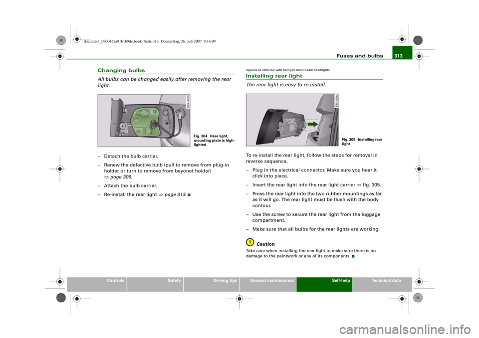
Changing bulbs
All bulbs can be changed easily after removing the rear
light.– Detach the bulb carrier.
– Renew the defective bulb (pull to remove from plug-in
holder or turn to remove from bayonet holder)
⇒page 305.
– Attach the bulb carrier.
– Re-install the rear light ⇒page 313.
Applies to vehicles: with halogen main beam headlightsInstalling rear light
The rear light is easy to re-install.To re-install the rear light, follow the steps for removal in
reverse sequence.
– Plug in the electrical connector. Make sure you hear it
click into place.
– Insert the rear light into the rear light carrier ⇒fig. 305.
– Press the rear light into the two rubber mountings as far
as it will go. The rear light must be flush with the body
contour.
– Use the screw to secure the rear light from the luggage
compartment.
– Make sure that all bulbs for the rear lights are working.
CautionTake care when installing the rear light to make sure there is no
damage to the paintwork or any of its components.
Fig. 304 Rear light,
mounting plate is high-
lighted
Fig. 305 Installing rear
light
document_0900452a81b1b9de.book Seite 313 Donnerstag, 26. Juli 2007 9:16 09