2008 Alfa Romeo Brera/Spider Instrument
[x] Cancel search: InstrumentPage 7 of 270
6
SAFETY
DEVICES
WARNING
LIGHTS AND
MESSAGES
IN AN
EMERGENCY
CAR
MAINTENANCE
TECHNICAL
SPECIFICATIONS
INDEX
DASHBOARD
AND
CONTROLS
CORRECT USE
OF THE CAR
D D
A A
S S
H H
B B
O O
A A
R R
D D
A A
N N
D D
C C
O O
N N
T T
R R
O O
L L
S S
CEILING LIGHTS ................................................. 75
CONTROLS ........................................................ 77
INTERIOR FITTINGS............................................. 80
FIXED PANORAMA ROOF ..................................... 84
DOORS ............................................................ 86
POWER WINDOWS ............................................ 88
BOOT ............................................................... 90
BONNET............................................................ 96
ROOF RACK/SKI RACK ....................................... 97
HEADLIGHTS...................................................... 97
ABS SYSTEM .................................................... 99
VDC SYSTEM .................................................... 100
EOBD SYSTEM .................................................. 104
SOUND SYSTEM ................................................ 104
ACCESSORIES PURCHASED BY THE OWNER .......... 105
INSTALLATION OF ELECTRIC/ELECTRONIC DEVICES .. 105
PARKING SENSORS ............................................ 106
TYRE PRESSURE MONITORING SYSTEM (T.P.M.S.) .. 109
AT THE FILLING STATION ..................................... 112
PROTECTING THE ENVIRONMENT ......................... 114 DASHBOARD...................................................... 7
INSTRUMENT PANEL .......................................... 8
SYMBOLS ........................................................ 9
THE ALFA ROMEO CODE SYSTEM.......................... 9
ELECTRONIC KEY ............................................... 11
ALARM ............................................................ 17
IGNITION DEVICE................................................ 19
INSTRUMENTS ................................................... 22
RECONFIGURABLE MULTIFUNCTION DISPLAY .......... 26
SEATS .............................................................. 41
HEAD RESTRAINTS.............................................. 44
STEERING WHEEL .............................................. 45
REARVIEW MIRRORS .......................................... 46
CLIMATE CONTROL SYSTEM ................................ 49
MANUAL CLIMATE CONTROL SYSTEM ................... 51
AUTOMATIC TWO-ZONE CLIMATE CONTROL SYSTEM 54
ADDITIONAL HEATER .......................................... 64
EXTERNAL LIGHTS ............................................. 65
WINDOW WASHING .......................................... 68
CRUISE CONTROL .............................................. 72
Page 8 of 270
7
SAFETY
DEVICES
WARNING
LIGHTS AND
MESSAGES
IN AN
EMERGENCY
CAR
MAINTENANCE
TECHNICAL
SPECIFICATIONS
INDEX
DASHBOARD
AND
CONTROLS
CORRECT USE
OF THE CAR
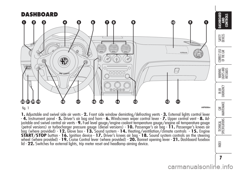
DASHBOARD
A0F0056mfig. 1
1.Adjustable and swivel side air vents - 2.Front side window demisting/defrosting vents - 3.External lights control lever
-4.Instrument panel - 5.Driver’s air bag and horn - 6.Windscreen wiper control lever - 7.Upper central vent - 8.Ad-
justable and swivel central air vents - 9.Fuel level gauge/engine coolant temperature gauge/engine oil temperature gauge
(petrol versions) or turbocharger pressure gauge (diesel versions) - 10.Passenger’s air bag - 11.Passenger’s knees air
bag (where provided) - 12.Glove box - 13.Sound system - 14.Heating/ventilation/climate controls - 15.Engine
START/STOPbutton - 16.Ignition device - 17.Driver’s knees air bag - 18.Sound system controls on the steering
wheel (where provided) - 19.Cruise Control lever (where provided) - 20.Bonnet opening lever - 21.Dashboard fusebox
lid - 22.Switches for external lights, trip meter reset and headlamp aiming device.
Page 9 of 270
8
SAFETY
DEVICES
WARNING
LIGHTS AND
MESSAGES
IN AN
EMERGENCY
CAR
MAINTENANCE
TECHNICAL
SPECIFICATIONS
INDEX
DASHBOARD
AND
CONTROLS
CORRECT USE
OF THE CAR
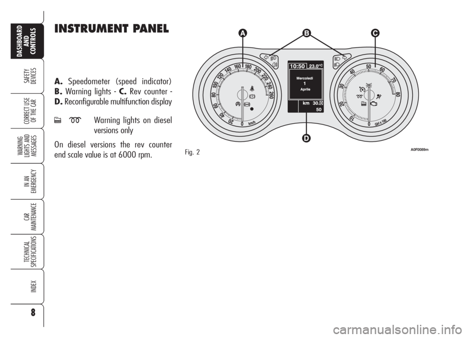
INSTRUMENT PANEL
A.Speedometer (speed indicator)
B.Warning lights - C.Rev counter -
D.Reconfigurable multifunction display
cmWarning lights on diesel
versions only
On diesel versions the rev counter
end scale value is at 6000 rpm.
Fig. 2A0F0089m
Page 19 of 270

18
SAFETY
DEVICES
WARNING
LIGHTS AND
MESSAGES
IN AN
EMERGENCY
CAR
MAINTENANCE
TECHNICAL
SPECIFICATIONS
INDEX
DASHBOARD
AND
CONTROLS
CORRECT USE
OF THE CAR
HOW TO DEACTIVATE
THE ALARM
Press button Ë. The system will react as
follows (with the exception of certain
markets):
❒two brief flashes of the direction in-
dicators;
❒two brief “beeps”;
❒door unlocking.
The alarm can be deactivated by fitting
the electronic key into the ignition
switch.
IMPORTANTOn certain versions any
attempt to break in detected by the sys-
tem will be indicated by a warning mes-
sage on the instrument panel display
when fitting the electronic key into the
ignition switch.VOLUMETRIC PROTECTION/
ANTI-RAISING SENSORS
To make sure that the protection sensors
are working properly, check that win-
dows are shut.
This function can be cut out (for exam-
ple if you leave animals on the car) by
pressing button A-fig. 12on the front
ceiling light within 1 minute after in-
strument panel turning off.
When this function is off the button led
will turn on. Volumetric protection/an-
ti-raising sensors cut out shall be re-
peated at each instrument panel turning
off. Surveillance
When the system has been turned on,
the led A-fig. 11will flash to indicate
that the system is in the surveillance
mode. The led will flash continuously
while the system is under surveillance.
IMPORTANTOperation of the alarm
is adapted at the origin to the regula-
tions of the different countries.
Self-diagnosis and monitoring
of doors/bonnet/boot
If, after the alarm has been activated, a
second acoustic signal is heard, turn the
system off by pressing button
Ë, check
for proper locking of doors, bonnet and
boot, then turn the system on again by
pressing button
Á.
Otherwise if a door or bonnet/boot lid
is not correctly closed it will not be con-
trolled by the system. If the control sig-
nal is repeated when the doors and bon-
net/boot are closed properly this means
that the self-diagnosis function has de-
tected a system operating fault, in which
case it is necessary to contact Alfa
Romeo Authorized Services.
A0F0086mfig. 12
Page 21 of 270

20
SAFETY
DEVICES
WARNING
LIGHTS AND
MESSAGES
IN AN
EMERGENCY
CAR
MAINTENANCE
TECHNICAL
SPECIFICATIONS
INDEX
DASHBOARD
AND
CONTROLS
CORRECT USE
OF THE CAR
IMPORTANTIf when fitting the elec-
tronic key into the ignition device, sym-
bol
Yis displayed (on certain versions
together with a message) check
whether the electronic key is the prop-
er one and then try to refit it into the
ignition device. If the problem persists
contact Alfa Romeo Authorized Services.
TURNING THE INSTRUMENT
PANEL OFF
With the engine off and brake and clutch
pedal released, press button
START/STOPor take the electronic
key out of the ignition device.
Few seconds after the instrument pan-
el will gradually turn off.
IMPORTANTIf when removing the
electronic key from the ignition device
the instrument panel stays on, contact
Alfa Romeo Authorized Services.
TURNING THE INSTRUMENT
PANEL ON
Proceed as follows:
❒fit the electronic key into the ignition
device;
❒if the electronic key is fitted yet,
press button START/STOPwith-
out pressing the clutch or brake ped-
al.
To safeguard the battery, when leaving
the car with the instrument panel on,
electric and electronic devices will be de-
activated after approx. 1 hour.
IMPORTANT Fit the electronic key in-
to the ignition device completely until
it locks into place.
IMPORTANTIf when fitting the elec-
tronic key into the ignition device the in-
strument panel stays off, contact Alfa
Romeo Authorized Services.
A0F0028mfig. 14
ENGINE STARTING
See paragraph “Engine starting” in sec-
tion “Correct use of the car”.
START/STOP BUTTON
fig. 14
ButtonSTART/STOP, set on the
dashboard, controls car electric systems
and engine starting/stopping.
ButtonSTART/STOPis fitted with
knurled ring and led. When the led and
the instrument panel are on, the engine
can be started.
Page 22 of 270

21
SAFETY
DEVICES
WARNING
LIGHTS AND
MESSAGES
IN AN
EMERGENCY
CAR
MAINTENANCE
TECHNICAL
SPECIFICATIONS
INDEX
DASHBOARD
AND
CONTROLS
CORRECT USE
OF THE CAR
It is absolutely forbidden
to carry out whatever
after-market operation involv-
ing steering system or steering
column modifications (e.g.: in-
stallation of anti-theft device)
that could badly affect perfor-
mance and safety, cause the
lapse of warranty and also re-
sult in non-compliance of the car
with homologation require-
ments.
WARNING
Disengaging
The steering column lock will disengage
after fitting the electronic key into the
ignition device.
IMPORTANTSwitching the engine off
when the car is running will not engage
the steering column lock till next switch-
ing off of the engine with car stopped. In
this event a dedicated message will be dis-
played.
IMPORTANTSteering column lock fail-
ure is indicated by symbol + message on
the display. In this event contact Alfa
Romeo Authorized Services.STEERING COLUMN LOCK
Engaging
The steering column lock will engage
5 seconds after removing the electron-
ic key from the ignition device and if the
following conditions are present:
❒engine off;
❒ instrument panel off with car at a
standstill;
❒electronic key removed from ignition
device.IMPORTANTIf after turning the in-
strument panel on and/or starting the en-
gine, the display shows the message “Car
protection system not available”, repeat
the operation using the moving the steer-
ing wheel to facilitate steering column un-
locking. Displaying of the warning mes-
sage will not impair steering column lock
regular operation.
Page 23 of 270

22
SAFETY
DEVICES
WARNING
LIGHTS AND
MESSAGES
IN AN
EMERGENCY
CAR
MAINTENANCE
TECHNICAL
SPECIFICATIONS
INDEX
DASHBOARD
AND
CONTROLS
CORRECT USE
OF THE CAR
FUEL GAUGE fig. 15
The pointer shows the amount of fuel
left in the tank.
0- tank empty.
1- tank full (see the indications given
in paragraph “At the filling station").
The fuel gauge warning light turns on to
indicate that approx. 10 litres of fuel are
left in the tank. When range falls below
50 km (or 31 mi) the display will show
a dedicated warning message.
If warning light
Kstarts
flashing when travel-
ling, contact Alfa Romeo
Authorized Services.
A0F00177mfig. 15
INSTRUMENTS
REV. COUNTER
Rev counter shows engine rpm. The dan-
ger zone (red) indicates excessive high
engine revs. Do not drive for long peri-
ods with the pointer in this area.
IMPORTANTThe electronic injection
control system gradually shuts off the
flow of fuel when the engine is “over-
revving” (rev counter pointer in red
area) resulting in a gradual loss of en-
gine power, in order to bring back rpm
below the safety limit.The rev counter may, when the engine is
idling, indicate gradual or sudden increase
of engine revs as the case may be; such
behaviour is normal and must not be in-
terpreted as a faulty condition as it occurs
during normal operation, for instance when
climate control or electric fan are switched
on. In particular, slow revs variation helps
keep the battery charged.
Page 26 of 270

25
SAFETY
DEVICES
WARNING
LIGHTS AND
MESSAGES
IN AN
EMERGENCY
CAR
MAINTENANCE
TECHNICAL
SPECIFICATIONS
INDEX
DASHBOARD
AND
CONTROLS
CORRECT USE
OF THE CAR
AUTOMATIC INSTRUMENT
PANEL LIGHT DIMMER
To give max. visibility and comfort un-
der whatever driving conditions (e.g.:
lights on in daylight, tunnels, etc…), the
speedometer is fitted with a sensor for
adjusting automatically, after fitting the
electronic key into the ignition device and
pressing button START/STOP, the
light intensity of the instrument panel dis-
play, sound system display, climate con-
trol system display, radionavigation sys-
tem display (where provided), and in-
struments (i.e.: fuel level gauge, engine
oil temperature gauge for petrol versions
or turbocharger pressure gauge for diesel
versions, and engine coolant temperature
gauge).
TRIP METER RESET fig. 19
To reset the trip meter, keep button A
pressed for a few seconds.
MANUAL INSTRUMENT
PANEL LIGHT DIMMER
With this function it is possible to adjust
on 8 levels the light intensity of the indi-
cations given on the instrument panel dis-
play, sound system display, climate con-
trol system display, radionavigation sys-
tem display (where provided), and in-
struments (i.e.: fuel level gauge, engine
oil temperature gauge for petrol versions
or turbocharger pressure gauge for diesel
versions, and engine coolant temperature
gauge).
To increase light intensity press briefly
button+on the left-hand stalk, to re-
duce it press button –: the display will
show an indication and a figure corre-
sponding to the current light intensity
level. This screen will be displayed for
a few seconds and then it will go off.
A0F0072mfig. 19