Page 157 of 185

155
Changing a wheel
TROUBLESHOOTING
8
4. OPERATING PROCEDURE Do not extend the jack until you have started
unscrewing the bolts on the wheel to be
changed and have placed the chock under
the wheel diagonally opposite.
- Remove the trim pulling it using the
embellisher remover.
- Loosen the wheel bolts and start unscrewing them.
- Place the jack in contact with the locating point provided, the one which is
closest to the wheel to be changed.
Ensure that the jack is straight and that the base of the jack is fully in contact
with the ground.
- Extend the jack to lift the wheel clear of the ground.
- Resume and complete the unscrewing of the wheel bolts.
- Remove the bolts and remove the wheel. Special tools for vehicles fitted
with alloy wheels
If your vehicle has wheels with alloy rims:
- The embellisher is removed using the
alloy wheel embellisher remover.
� � �-� � �E�a�c�h� �w�h�e�e�l� �i�s� �fi� �t�t�e�d� �w�i�t�h� �a�n� �a�n�t�i�-�t�h�e�f�t� �b�o�l�t�.�
- These bolts can be loosened using your anti-theft socket (given to you
on delivery of your vehicle) and the
wheelbrace.
Page 158 of 185
Changing a wheel - Lower the vehicle completely by folding the jack, then remove the jack.
- Tighten the bolts again using the wheelbrace, tighten them fully without
forcing them.
- Place the wheel to be repaired in the carrier. - Secure the carrier on the hook then
raise the carrier using the bolt and the
wheel brace.
- Remember to close the flap, located on the sill.
- Store the trim in the vehicle.
Never go underneath the vehicle
when it is supported only by the jack.
Never use a screwdriver in place of the
wheelbrace.
5. FITTING THE SPARE WHEEL
- Position the wheel on the hub and start
tightening the wheel bolts by hand.
- Carry out an initial tightening of the bolts using the wheelbrace.
Page 159 of 185

157
Snow screen
TROUBLESHOOTING
8
6. REFITTING THE REPAIRED WHEEL
The wheel is refitted as described in step 5,
not forgetting to refit the wheel trim.
The spare wheel is not designed to be used
over long distances. Have the tightening of
the bolts and the tyre pressure checked by a
CITROËN dealer as soon as possible. Also,
have the original wheel repaired and refitted
by a CITROËN dealer as soon as possible. Refer to the "Identification features"
section of chapter 9 to locate the tyre
label.
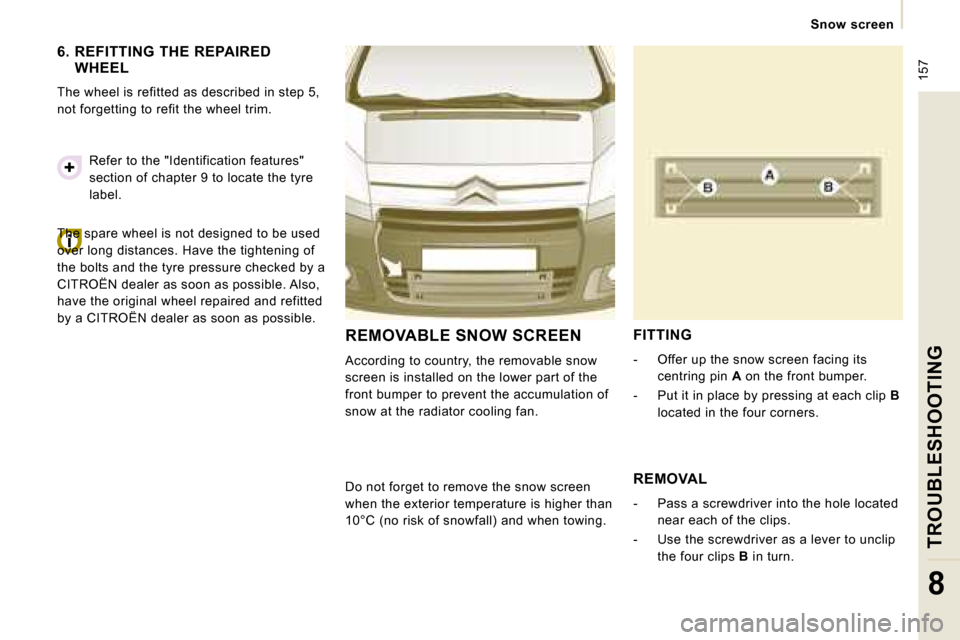
REMOVABLE SNOW SCREEN
According to country, the removable snow
screen is installed on the lower part of the
front bumper to prevent the accumulation of
snow at the radiator cooling fan.
FITTING
- Offer up the snow screen facing its
centring pin A on the front bumper.
- Put it in place by pressing at each clip B
located in the four corners.
Do not forget to remove the snow screen
when the exterior temperature is higher than
10°C (no risk of snowfall) and when towing. REMOVAL
- Pass a screwdriver into the hole located
near each of the clips.
- Use the screwdriver as a lever to unclip the four clips B in turn.
Page 160 of 185

157
Snow screen
TROUBLESHOOTING
8
6. REFITTING THE REPAIRED WHEEL
The wheel is refitted as described in step 5,
not forgetting to refit the wheel trim.
The spare wheel is not designed to be used
over long distances. Have the tightening of
the bolts and the tyre pressure checked by a
CITROËN dealer as soon as possible. Also,
have the original wheel repaired and refitted
by a CITROËN dealer as soon as possible. Refer to the "Identification features"
section of chapter 9 to locate the tyre
label.
REMOVABLE SNOW SCREEN
According to country, the removable snow
screen is installed on the lower part of the
front bumper to prevent the accumulation of
snow at the radiator cooling fan.
FITTING
- Offer up the snow screen facing its
centring pin A on the front bumper.
- Put it in place by pressing at each clip B
located in the four corners.
Do not forget to remove the snow screen
when the exterior temperature is higher than
10°C (no risk of snowfall) and when towing. REMOVAL
- Pass a screwdriver into the hole located
near each of the clips.
- Use the screwdriver as a lever to unclip the four clips B in turn.
Page 167 of 185

164
Changing a fuse
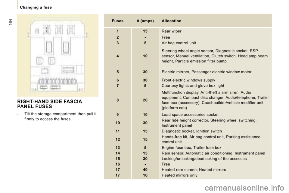
RIGHT-HAND SIDE FASCIA PANEL FUSES
- Tilt the storage compartment then pull it firmly to access the fuses.
Fuses A (amps) Allocation
1 15 Rear wiper
2 - Free
3 5 Air bag control unit
4 10 Steering wheel angle sensor, Diagnostic socket, ES
P
sensor, Manual ventilation, Clutch switch, Headlamp beam
height, Particle emission filter pump
5 30 Electric mirrors, Passenger electric window mot or
6 30 Front electric windows supply
7 5 Courtesy lights and glove box light
8 20 Multifunction display, Anti-theft alarm siren, Aud
io
equipment, Compact disc changer, Audio/telephone, T railer
fuse box (accessory), Coachbuilder/vehicle modifier unit
(platform cab)
9 10 Load space accessories socket
10 30 Rear ride height corrector, Steering wheel switchi
ng,
Instrument panel
11 15 Diagnostic socket, Ignition switch
12 15 Hands-free kit, Air bag control unit, Parking assi
stance
control unit
13 5 Engine fuse box, Trailer fuse box
14 15 Rain sensor, Automatic air conditioning, Instru ment panel
15 30 Locking/unlocking/deadlocking of the accesses
16 - Free
17 40 Heated rear screen, Heated mirrors
17 10 Heated mirrors only
Page 172 of 185
Having your vehicle towed
TROUBLESHOOTING
8
Without lifting
(4 wheels on the road)
You should always use a towbar.
From the front
- Unclip the cover by pressing the bottom part.
- Screw in the removable towing eye until it locks.
BEING TOWED
Lifting (2 wheels on the road only)
It is preferable to raise the vehicle using
professional lifting equipment.
From the rear
- Unclip the cover using a coin or the flat part of the towing eye,
- Screw in the removable towing eye until it locks. When towing with the engine switched
off, there is no braking or steering
assistance.
Vehicles fitted with a manual
gearbox (diesel version)
In the case of vehicles fitted with a manual
gearbox, the gear lever must be in the
neutral position. Failure to observe this
special condition may result in damage
to certain braking components and the
absence of braking assistance the next time
the engine is started.
Page 174 of 185
Dimensions
TECHNICAL DATA
9 * Value for rear suspension.
L1 L2
H1 H1 H2
L Overall length 4 805 to 4 813 5 135 to 5 143
H Overall height 1 894 * /1 942 2 204 * /2 276
A Wheelbase 3 000 3 122
B Front overhang 975
C Rear overhang 830 to 838 1 038 to 1 046
D Overall width:
on panel 1 870
with mouldings 1 895
with mirrors folded 1 986
with mirrors unfolded 2 194
E Width of front tracks 1 562 to 1 570
F Width of rear tracks 1 596 to 1 604
I Length of interior floor 2 254 2 584
J Maximum interior height under roof 1 449 1 750
K Maximum interior width 1 600
M Interior width between wheel arches 1 245
Turning circle pitch diameter between kerbs (m) 12.18 12.59
Maximum loads (kg)
Payload 1 000 to 1 200
On roof 170
m 3
5 6 7
DIMENSIONS (MM)
The vehicle is available in 2 lengths (L1, L2) and 2 heights
(H1, H2), refer to the tables:
Page 178 of 185
175
Dimensions
TECHNICAL DATA
9
PLATFORM CAB (mm)
L2
L Overall length 5 016
A Wheelbase 3 122
B Front overhang 975
C Rear overhang 920
Max passable rear overhang 1 420
D Overall width (excluding mirrors) 1 895
E Width of front tracks 1 574
F Width of rear tracks 1 574
- Gross vehicle weight -
- Max weight at the front 1 400
- Max weight at the rear 1 700