Page 50 of 676

1 - 10
GEN
INFO
CONTROL FUNCTIONS
EC150000
CONTROL FUNCTIONS
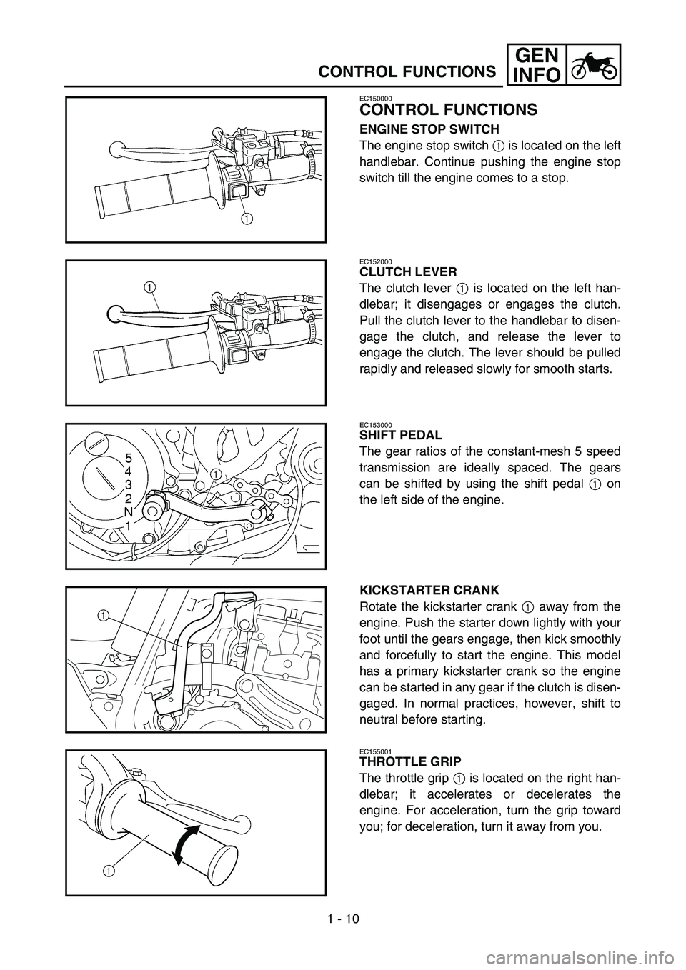
ENGINE STOP SWITCH
The engine stop switch 1 is located on the left
handlebar. Continue pushing the engine stop
switch till the engine comes to a stop.
EC152000
CLUTCH LEVER
The clutch lever 1 is located on the left han-
dlebar; it disengages or engages the clutch.
Pull the clutch lever to the handlebar to disen-
gage the clutch, and release the lever to
engage the clutch. The lever should be pulled
rapidly and released slowly for smooth starts.
EC153000
SHIFT PEDAL
The gear ratios of the constant-mesh 5 speed
transmission are ideally spaced. The gears
can be shifted by using the shift pedal 1 on
the left side of the engine.
KICKSTARTER CRANK
Rotate the kickstarter crank 1 away from the
engine. Push the starter down lightly with your
foot until the gears engage, then kick smoothly
and forcefully to start the engine. This model
has a primary kickstarter crank so the engine
can be started in any gear if the clutch is disen-
gaged. In normal practices, however, shift to
neutral before starting.
1
EC155001
THROTTLE GRIP
The throttle grip 1 is located on the right han-
dlebar; it accelerates or decelerates the
engine. For acceleration, turn the grip toward
you; for deceleration, turn it away from you.
Page 52 of 676

1 - 11
GEN
INFO
CONTROL FUNCTIONS
EC156000
FRONT BRAKE LEVER
The front brake lever 1 is located on the right
handlebar. Pull it toward the handlebar to acti-
vate the front brake.
EC157000
REAR BRAKE PEDAL
The rear brake pedal 1 is located on the right
side of the machine. Press down on the brake
pedal to activate the rear brake.
EC158001
FUEL COCK
The fuel cock supplies fuel from the tank to
carburetor while filtering the fuel. The fuel cock
has the two positions:
OFF: With the lever in this position, fuel will not
flow. Always return the lever to this posi-
tion when the engine is not running.
ON: With the lever in this position, fuel flows
to the carburetor. Normal riding is done
with the lever in this position.
COLD STARTER KNOB
When cold, the engine requires a richer air-fuel
mixture for starting. A separate starter circuit,
which is controlled by the cold starter knob 1,
supplies this mixture. Pull the cold starter knob
out to open the circuit for starting. When the
engine has warmed up, push it in to close the
circuit.
1
HOT STARTER LEVER
The hot starter lever 1 is used when starting a
warm engine.
Use the hot starter lever when starting the
engine again immediately after it was stopped
(the engine is still warm). Pulling the hot starter
lever injects secondary air to thin the air-fuel
mixture temporarily, allowing the engine to be
started more easily.
Page 70 of 676

1 - 19
GEN
INFO
CLEANING AND STORAGE
EC1B0000
CLEANING AND STORAGE
EC1B1000
CLEANING
Frequent cleaning of your machine will
enhance its appearance, maintain good overall
performance, and extend the life of many com-
ponents.
1. Before washing the machine, block off the
end of the exhaust pipe to prevent water
from entering. A plastic bag secured with a
rubber band may be used for this purpose.
2. If the engine is excessively greasy, apply
some degreaser to it with a paint brush. Do
not apply degreaser to the chain, sprock-
ets, or wheel axles.
3. Rinse the dirt and degreaser off with a gar-
den hose; use only enough pressure to do
the job.
CAUTION:
Excessive hose pressure may cause water
seepage and contamination of wheel bear-
ings, front forks, brakes and transmission
seals. Many expensive repair bills have
resulted from improper high pressure
detergent applications such as those avail-
able in coin-operated car washers.
4. After the majority of the dirt has been
hosed off, wash all surfaces with warm
water and a mild detergent. Use an old
toothbrush to clean hard-to-reach places.
5. Rinse the machine off immediately with
clean water, and dry all surfaces with a soft
towel or cloth.
6. Immediately after washing, remove excess
water from the chain with a paper towel
and lubricate the chain to prevent rust.
7. Clean the seat with a vinyl upholstery
cleaner to keep the cover pliable and
glossy.
8. Automotive wax may be applied to all
painted or chromed surfaces. Avoid combi-
nation cleaner-waxes, as they may contain
abrasives.
9. After completing the above, start the
engine and allow it to idle for several min-
utes.
Page 176 of 676
3 - 5
INSP
ADJ
EC350000
ENGINE
COOLANT LEVEL INSPECTION
WARNING
Do not remove the radiator cap
1, drain
bolt and hoses when the engine and radia-
tor are hot. Scalding hot fluid and steam
may be blown out under pressure, which
could cause serious injury.
When the engine has cooled, place a thick
towel over the radiator cap, slowly rotate
the cap counterclockwise to the detent.
This procedure allows any residual pres-
sure to escape. When the hissing sound
has stopped, press down on the cap while
turning counterclockwise and remove it.
CAUTION:
Hard water or salt water is harmful to the
engine parts. You may use distilled water, if
you can’t get soft water.
1. Place the machine on a level place, and
hold it in an upright position.
2. Remove:
Radiator cap
3. Check:
Coolant level a
Coolant level low → Add coolant.
1Radiator
1a
ENGINE/COOLANT LEVEL INSPECTION
Page 214 of 676

3 - 23
INSP
ADJ
CHASSIS/BRAKE SYSTEM AIR BLEEDING
EC360000
CHASSIS
EC361012
BRAKE SYSTEM AIR BLEEDING
WARNING
Bleed the brake system if:
The system has been disassembled.
A brake hose has been loosened or
removed.
The brake fluid is very low.
The brake operation is faulty.
A dangerous loss of braking performance
may occur if the brake system is not prop-
erly bled.
1. Remove:
Brake master cylinder cap
Diaphragm
Reservoir float (front brake)
Protector (rear brake)
2. Bleed:
Brake fluid
È
Front
ÉRear
Air bleeding steps:
a. Add proper brake fluid to the reservoir.
b. Install the diaphragm. Be careful not to
spill any fluid or allow the reservoir to
overflow.
c. Connect the clear plastic tube 2 tightly
to the caliper bleed screw 1.
d. Place the other end of the tube into a
container.
e. Slowly apply the brake lever or pedal
several times.
f. Pull the lever in or push down on the
pedal. Hold the lever or pedal in position.
g. Loosen the bleed screw and allow the
lever or pedal to travel towards its limit.
h. Tighten the bleed screw when the lever
or pedal limit has been reached; then
release the lever or pedal.
T R..
Bleed screw:
6 Nm (0.6 m kg, 4.3 ft lb)
i. Repeat steps (e) to (h) until of the air
bubbles have been removed from the
system.
È
É
Page 270 of 676
4 - 5
ENG
ASSEMBLY AND INSTALLATION
Silencer and exhaust pipe
1. Install:
Gasket
Exhaust pipe 1
Nut (exhaust pipe) 2
NOTE:
First, temporarily install both nuts, then tighten
either of these nuts to 13 Nm (1.3 mkg,
9.4 ftlb) and the other to 20 Nm (2.0 mkg,
14 ftlb) and then come back to the first one
and retighten it to 20 Nm (2.0 mkg,
14 ftlb).
T R..20 Nm (2.0 m · kg, 14 ft · lb)
2. Install:
Silencer clamp 1
Gasket 2
Silencer 3
Washer 4
Bolt (silencer) 5
NOTE:
Install the gasket with its meshed area a
toward the exhaust pipe side.
The gasket should be installed according to
the dimension shown.
4
5
1
2a
2.5 ~ 3.5 mm (0.10 ~ 0.14 in)
T R..16 Nm (1.6 m · kg, 11 ft · lb)
T R..30 Nm (3.0 m · kg, 22 ft · lb)
EXHAUST PIPE AND SILENCER
Page 274 of 676

4 - 7
ENGRADIATOR
EC456000
HANDLING NOTE
WARNING
Do not remove the radiator cap when the
engine and radiator are hot. Scalding hot
fluid and steam may be blown out under
pressure, which could cause serious
injury.
When the engine has cooled, open the radi-
ator cap by the following procedure:
Place a thick rag, like a towel, over the radi-
ator cap, slowly rotate the cap counter-
clockwise to the detent. This procedure
allows any residual pressure to escape.
When the hissing sound has stopped,
press down on the cap while turning coun-
terclockwise and remove it.
EC454000
INSPECTION
EC444100
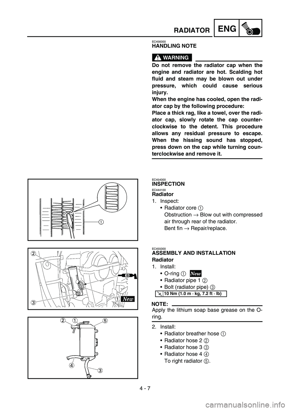
Radiator
1. Inspect:
Radiator core 1
Obstruction → Blow out with compressed
air through rear of the radiator.
Bent fin → Repair/replace.
EC455000
ASSEMBLY AND INSTALLATION
Radiator
1. Install:
O-ring 1
Radiator pipe 1 2
Bolt (radiator pipe) 3
NOTE:
Apply the lithium soap base grease on the O-
ring.
2. Install:
Radiator breather hose 1
Radiator hose 2 2
Radiator hose 3 3
Radiator hose 4 4
To right radiator 5.
T R..10 Nm (1.0 m · kg, 7.2 ft · lb)
Page 418 of 676
4 - 79
ENGKICK SHAFT AND SHIFT SHAFT
3. Install:
Spring guide 1
NOTE:
Slide the spring guide into the kick shaft, make
sure the groove a in the spring guide fits on
the stopper of the torsion spring.
4. Install:
Kick shaft assembly 1
Washer 2
NOTE:
Apply the molybdenum disulfide grease on
the contacting surfaces of the kick shaft stop-
per a and kick shaft ratchet wheel guide 3.
Apply the engine oil on the kick shaft.
Slide the kick shaft assembly into the crank-
case and make sure the kick shaft stopper a
fits into the kick shaft ratchet wheel guide.
5. Hook:
Torsion spring 1
NOTE:
Turn the torsion spring clockwise and hook
into the proper hole a in the crankcase.
Kick idle gear
1. Install:
Kick idle gear 1
Washer 2
Circlip 3
NOTE:
Apply the engine oil on the kick idle gear
inner circumference.
Install the kick idle gear with its depressed
side a toward you.