Page 26 of 676
GEN
INFO
1 - 1
DESCRIPTION
EC100000
GENERAL INFORMATION
EC110000
DESCRIPTION
1Clutch lever
2Hot starter lever
3Front brake lever
4Throttle grip
5Radiator cap
6Fuel tank cap
7Engine stop switch
8Kickstarter crank
9Fuel tank
0Radiator
ACoolant drain bolt
BRear brake pedal
CValve joint
DFuel cock
ECold starter knob
FDrive chain
GAir filter
HOil level check window
IShift pedal
JFront forkNOTE:
The machine you have purchased may differ
slightly from those shown in the following.
Designs and specifications are subject to
change without notice.
Page 200 of 676

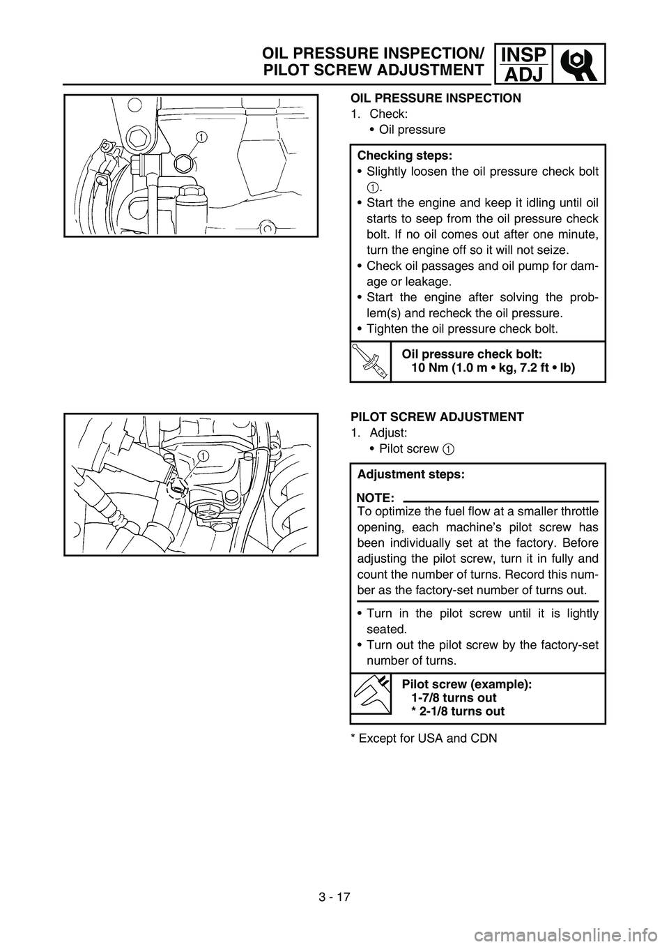
3 - 17
INSP
ADJ
OIL PRESSURE INSPECTION
1. Check:
Oil pressure
Checking steps:
Slightly loosen the oil pressure check bolt
1.
Start the engine and keep it idling until oil
starts to seep from the oil pressure check
bolt. If no oil comes out after one minute,
turn the engine off so it will not seize.
Check oil passages and oil pump for dam-
age or leakage.
Start the engine after solving the prob-
lem(s) and recheck the oil pressure.
Tighten the oil pressure check bolt.
T R..
Oil pressure check bolt:
10 Nm (1.0 m kg, 7.2 ft lb)
PILOT SCREW ADJUSTMENT
1. Adjust:
Pilot screw 1
* Except for USA and CDNAdjustment steps:
NOTE:
To optimize the fuel flow at a smaller throttle
opening, each machine’s pilot screw has
been individually set at the factory. Before
adjusting the pilot screw, turn it in fully and
count the number of turns. Record this num-
ber as the factory-set number of turns out.
Turn in the pilot screw until it is lightly
seated.
Turn out the pilot screw by the factory-set
number of turns.
Pilot screw (example):
1-7/8 turns out
* 2-1/8 turns out
OIL PRESSURE INSPECTION/
PILOT SCREW ADJUSTMENT
Page 258 of 676
3 - 45
INSP
ADJ
ELECTRICAL/SPARK PLUG INSPECTION
EC370000
ELECTRICAL
EC371001
SPARK PLUG INSPECTION
1. Remove:
Spark plug
2. Inspect:
Electrode 1
Wear/damage → Replace.
Insulator color 2
Normal condition is a medium to light tan
color.
Distinctly different color → Check the
engine condition.
NOTE:
When the engine runs for many hours at low
speeds, the spark plug insulator will become
sooty, even if the engine and carburetor are in
good operating condition.
3. Measure:
Plug gap a
Use a wire gauge or thickness gauge.
Out of specification → Regap.
4. Clean the plug with a spark plug cleaner if
necessary.
Spark plug gap:
0.7 ~ 0.8 mm (0.028 ~ 0.031 in)
5. Tighten:
Spark plug
NOTE:
Before installing a spark plug, clean the gas-
ket surface and plug surface.
Finger-tighten a the spark plug before torqu-
ing to specification b.
T R..13 Nm (1.3 m · kg, 9.4 ft · lb)
Page 260 of 676
3 - 46
INSP
ADJ
IGNITION TIMING CHECK
IGNITION TIMING CHECK
1. Remove:
Timing mark accessing screw 1
2. Attach:
Timing light
Inductive tachometer
To the ignition coil lead (orange lead 1).
Timing light:
YM-33277-A/90890-03141
1
3. Adjust:
Engine idling speed
Refer to “ENGINE IDLING SPEED
ADJUSTMENT” section.
4. Check:
Ignition timing
Visually check the stationary pointer a is
within the firing range b on the rotor.
Incorrect firing range → Check rotor and
pickup assembly.
5. Install:
Timing mark accessing screw
Page 314 of 676

4 - 27
ENGCAMSHAFTS
Decompression system
1. Check:
Decompression system
Timing chain tensioner
1. Check:
While pressing the tensioner rod lightly
with fingers, use a thin screwdriver 1
and wind the tensioner rod up fully clock-
wise.
When releasing the screwdriver by press-
ing lightly with fingers, make sure that the
tensioner rod will come out smoothly.
If not, replace the tensioner assembly.
ASSEMBLY AND INSTALLATION
Camshaft
1. Install:
Exhaust camshaft 1
Intake camshaft 2 Checking steps:
Check that the decompression mecha-
nism cam 1 moves smoothly.
Check that the decompression mecha-
nism cam lever pin 2 projects from the
camshaft.
Installation steps:
Turn the crankshaft counterclockwise with
a wrench.
NOTE:
Apply the molybdenum disulfide oil on the
camshafts.
Apply the engine oil on the decompression
system.
Squeezing the decompression lever
allows the crankshaft to be turned easily.
Align the T.D.C. mark a on the rotor with
the align mark b on the crankcase cover
when piston is at T.D.C. on compression
stroke.
Page 628 of 676

7 - 2
TUN
CAUTION:
The carburetor is extremely sensitive to
foreign matter (dirt, sand, water, etc.).
During installation, do not allow foreign
matter to get into the carburetor.
Always handle the carburetor and its
components carefully. Even slight
scratches, bends or damage to carburetor
parts may prevent the carburetor from
functioning correctly. Carefully perform
all servicing with the appropriate tools
and without applying excessive force.
When the engine is stopped or when
riding at no load, do not open and close
the throttle unnecessarily. Otherwise, too
much fuel may be discharged, starting
may become difficult or the engine may
not run well.
After installing the carburetor, check that
the throttle operates correctly and opens
and closes smoothly.
Atmospheric conditions and carburetor
settings
The air density (i.e., concentration of oxygen
in the air) determines the richness or lean-
ness of the air/fuel mixture. Therefore, refer
to the above table for mixture settings.
That is:
•Higher temperature expands the air with its
resultant reduced density.
•Higher humidity reduces the amount of oxy-
gen in the air by so much of the water vapor
in the same air.
•Lower atmospheric pressure (at a high alti-
tude) reduces the density of the air.
Air temp. HumidityAir
pressure
(altitude)Mixture Setting
High High Low (high) Richer Leaner
Low Low High (low) Leaner Richer
SETTING