2007 YAMAHA YFM50R fuse
[x] Cancel search: fusePage 10 of 116

RIDING YOUR ATV ...................................... 7-1
GETTING TO KNOW YOUR ATV.............. 7-2
RIDE WITH CARE AND GOOD
JUDGEMENT ...........................................7-2
BE CAREFUL WHERE YOU RIDE ............ 7-8
TURNING YOUR ATV ............................. 7-12
CLIMBING UPHILL .................................. 7-13
RIDING DOWNHILL................................. 7-16
CROSSING A SLOPE.............................. 7-17
CROSSING THROUGH SHALLOW
WATER ..................................................7-18
RIDING OVER ROUGH TERRAIN .......... 7-19
SLIDING AND SKIDDING ........................ 7-20
WHAT TO DO IF... ................................... 7-21
WHAT TO DO... ....................................... 7-21
PERIODIC MAINTENANCE AND MINOR
REPAIR .......................................................... 8-1
Owner’s manual and tool kit ...................... 8-1
Periodic maintenance and lubrication
chart ........................................................ 8-3
Checking the spark plug ............................ 8-7
Engine oil .................................................. 8-8
Final gear oil ............................................ 8-11
Cleaning the air filter element ................. 8-12
Cleaning the spark arrester ..................... 8-15
Adjusting the carburetor .......................... 8-17
Adjusting the engine idling speed ........... 8-17
Checking the throttle cable free play ....... 8-18Valve clearance ....................................... 8-18
Checking the front and rear brake
shoes .....................................................8-19
Adjusting the front brake lever free
play ........................................................8-20
Adjusting the rear brake lever free play ... 8-22
Checking and lubricating the cables ........ 8-23
Checking and lubricating the front and
rear brake levers ....................................8-24
Checking the wheel bearings ................... 8-24
Lubricating the knuckle shafts ................. 8-24
Lubricating the steering shaft ................... 8-25
Battery ..................................................... 8-25
Replacing the fuse ................................... 8-28
Removing a wheel ................................... 8-28
Installing a wheel ..................................... 8-29
Troubleshooting ....................................... 8-31
Troubleshooting chart .............................. 8-32
CLEANING AND STORAGE ..........................9-1
Cleaning ..................................................... 9-1
Storage ...................................................... 9-2
SPECIFICATIONS .......................................10-1
CONSUMER INFORMATION.......................11-1
Identification numbers .............................. 11-1
Page 22 of 116

3-1
1
23
4
5
6
7
8
9
10
11
EBU17680
DESCRIPTION
EBU17690
Left view
EBU17700
Right view
1. Fuel cock
2. Fuse
3. Engine stop switch with cord (lanyard)
4. Footboard
5. Drive select lever
1
3
4
5
2
1. Spark arrester
2. Seat
3. Footboard
1
2
3
Page 99 of 116

8-28
1
2
3
4
5
6
78
9
10
11
that the frame is exposed to electrolyte or gas
expelled from the battery, the frame could suf-
fer structural and external damages.
EBU25242
Replacing the fuse
The fuse holder is located under the seat. (See
page 4-11.)
If the fuse is blown, replace it as follows.
1. Turn the key to “OFF” and turn off all electrical
circuits.
CAUTION:
ECB00640
To prevent accidental short-circuiting, turn off
the main switch when checking or replacing a
fuse.
2. Remove the blown fuse, and then install a
new fuse of the specified amperage.WARNING
EWB02171
Always use a fuse of the specified rating, and
never use a substitute object in place of the
proper fuse. An improper fuse or a substitute
object can cause damage to the electrical sys-
tem, which could lead to a fire.
3. Turn the key to “ON” and turn on the electrical
circuits to check if the devices operate.
4. If the fuse immediately blows again, have a
Yamaha dealer check the electrical system.
EBU25650
Removing a wheel
1. Loosen the wheel nuts.
1. Fuse
2. Spare fuse
1
2
Specified fuse:
5.0 A
Page 110 of 116

10-4
1
2
3
4
5
6
7
8
910
11
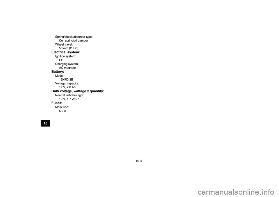
Spring/shock absorber type:
Coil spring/oil damper
Wheel travel:
56 mm (2.2 in)
Electrical system:
Ignition system:
CDI
Charging system:
AC magneto
Battery:
Model:
12N7D-3B
Voltage, capacity:
12 V, 7.0 Ah
Bulb voltage, wattage x quantity:
Neutral indicator light:
12 V, 1.7 W
×
1
Fuses:
Main fuse:
5.0 A
Page 113 of 116

INDEX
A
Accessories and loading ................................................ 6-7
Air filter element, cleaning ............................................ 8-12
B
Battery .................................................................. 5-6
,
8-25
Brake lever free play, adjusting the front...................... 8-20
Brake lever free play (rear), adjusting .......................... 8-22
Brake lever, front ............................................................ 4-6
Brake lever, rear............................................................. 4-6
Brake levers, checking and lubricating......................... 8-24
Brakes, front and rear .................................................... 5-3
Brake shoes, checking the front and rear .................... 8-19
C
Cables, checking and lubricating ................................. 8-23
Carburetor, adjusting.................................................... 8-17
Chassis fasteners........................................................... 5-6
Choke ........................................................................... 4-10
Cleaning ......................................................................... 9-1
D
Drive select lever............................................................ 4-7
E
Engine break-in .............................................................. 6-5
Engine, cold start ........................................................... 6-1
Engine idling speed ...................................................... 8-17
Engine oil ............................................................... 5-3
,
8-8
Engine, starting a warm ................................................. 6-3Engine stop switch ......................................................... 4-2
Engine stop switch with lanyard ..................................... 4-2
F
Final gear oil..........................................................5-3
,
8-11
Fuel .........................................................................4-8
,
5-3
Fuel cock ........................................................................ 4-9
Fuel tank cap.................................................................. 4-7
Fuse, replacing............................................................. 8-28
H
Handlebar switches ........................................................ 4-2
I
Identification numbers .................................................. 11-1
Indicator light .................................................................. 4-1
Instruments, lights and switches .................................... 5-6
K
Key identification number ............................................. 11-1
Knuckle shafts, lubricating ........................................... 8-24
L
Label locations ............................................................... 2-1
M
Main switch .................................................................... 4-1
Model label ................................................................... 11-2
N
Neutral indicator light ..................................................... 4-1
O
Owner’s manual and tool kit ........................................... 8-1