Page 664 of 794

5 - 63
CHAS
EC586000
HANDLING NOTE
WARNING
This shock absorber is provided with a
separate type tank filled with high-pressure
nitrogen gas. To prevent the danger of
explosion, read and understand the follow-
ing information before handling the shock
absorber.
The manufacturer can not be held respon-
sible for property damage or personal
injury that may result from improper han-
dling.
1. Never tamper or attempt to disassemble
the cylinder or the tank.
2. Never throw the shock absorber into an
open flame or other high heat. The
shock absorber may explode as a result
of nitrogen gas expansion and/or dam-
age to the hose.
3. Be careful not to damage any part of the
gas tank. A damaged gas tank will impair
the damping performance or cause a
malfunction.
4. Take care not to scratch the contact sur-
face of the piston rod with the cylinder;
or oil could leak out.
5. Never attempt to remove the plug at the
bottom of the nitrogen gas tank. It is
very dangerous to remove the plug.
6. When scrapping the shock absorber, fol-
low the instructions on disposal.
EC587000
NOTES ON DISPOSAL (YAMAHA DEALERS
ONLY)
Before disposing the shock absorber, be sure
to extract the nitrogen gas from valve 1. Wear
eye protection to prevent eye damage from
escaping gas and/or metal chips.
WARNING
To dispose of a damaged or worn-out
shock absorber, take the unit to your
Yamaha dealer for this disposal procedure.
REAR SHOCK ABSORBER
Page 694 of 794

6 - 8
–+ELECELECTRIC STARTING SYSTEM
EC624000
COUPLERS AND LEADS CONNECTION
INSPECTION
1. Check:
•Couplers and leads connection
Rust/dust/looseness/short-circuit →
Repair or replace.
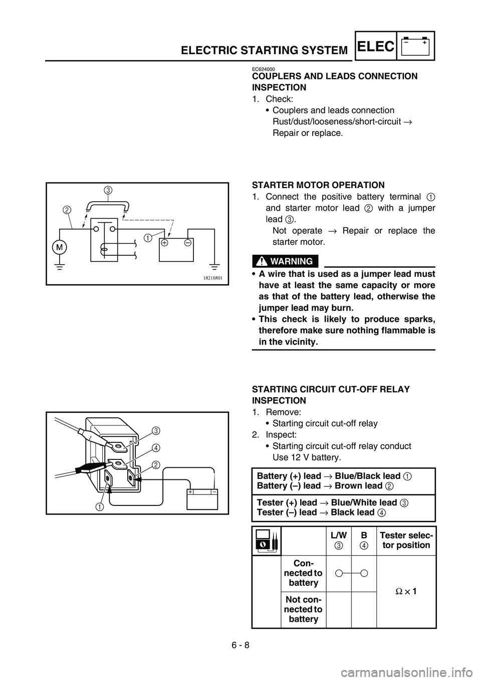
STARTER MOTOR OPERATION
1. Connect the positive battery terminal 1
and starter motor lead 2 with a jumper
lead 3.
Not operate → Repair or replace the
starter motor.
WARNING
A wire that is used as a jumper lead must
have at least the same capacity or more
as that of the battery lead, otherwise the
jumper lead may burn.
This check is likely to produce sparks,
therefore make sure nothing flammable is
in the vicinity.
STARTING CIRCUIT CUT-OFF RELAY
INSPECTION
1. Remove:
•Starting circuit cut-off relay
2. Inspect:
•Starting circuit cut-off relay conduct
Use 12 V battery.
Battery (+) lead
→ Blue/Black lead
1
Battery (–) lead
→ Brown lead
2
Tester (+) lead
→ Blue/White lead
3
Tester (–) lead
→ Black lead
4
L/W
3 B
4 Tester selec-
tor position
Con-
nected to
battery
Ω
×
×× × 1
Not con-
nected to
battery
2 4
3
1
Page 732 of 794
6 - 24
–+ELECLIGHTING SYSTEM
CHECKING THE TAILLIGHT (LEDs)
1. Disconnect the taillight coupler.
2. Connect two jumper leads 1 from the bat-
tery terminals to the respective coupler ter-
minal as shown.
3. Check:
•LED (for proper operation)
Does not light → Replace the taillight
assembly.
WARNING
A wire that is used as a jumper lead must
have at least the same capacity of the bat-
tery lead, otherwise the jumper lead may
burn.
This check is likely to produce sparks,
therefore, make sure no flammable gas or
fluid is in the vicinity.
Battery (+) terminal →
Blue lead
2
Battery (–) terminal →
Black lead
3
AC MAGNETO INSPECTION
1. Inspect:
•Lighting coil resistance
Out of specification → Replace.
Tester (+) lead
→ Yellow lead
1
Tester (–) lead
→ Ground
2
Lighting coil
resistanceTester selector
position
0.224 ~ 0.336
Ω
at 20 °C (68 °F)Ω
× 1
Page 746 of 794

7 - 1
TUN
EC700000
TUNING
EC710000
ENGINE
Carburetor setting
•The air/fuel mixture will vary depending on
atmospheric conditions. Therefore, it is nec-
essary to take into consideration the air pres-
sure, ambient temperature, humidity, etc.,
when adjusting the carburetor.
•Perform a test run to check for proper engine
performance (e.g., throttle response) and
spark plug(-s) discoloration or fouling. Use
these readings to determine the best possi-
ble carburetor setting.
NOTE:
It is recommended to keep a record of all car-
buretor settings and external conditions (e.g.,
atmospheric conditions, track/surface condi-
tions, lap times) to make future carburetor set-
ting easier.
WARNING
The carburetor is a part of the fuel line.
Therefore, be sure to install it in a well-
ventilated area, away from flammable
objects and any sources of fire.
Never look into the carburetor intake.
Flames may shoot out from the pipe if the
engine backfires while it is being started.
Gasoline may be discharged from the
accelerator pump nozzle when the carbu-
retor has been removed.
SETTING
Page 770 of 794
7 - 12
TUNSETTING
ÈAir spring characteristics in relation to oil level
change
ÉLoad
ÊStroke
1Max. oil level
2Standard oil level
3Min. oil levelÈ
EC727020
Spring preload adjustment
The spring preload is adjusted by installing the
adjustment washer 1
between the fork spring
2
and damper rod 3
.
CAUTION:
Do not install three or more adjustment
washers for each front fork.
WARNING
Always adjust each front fork to the same
setting. Uneven adjustment can cause poor
handling and loss of stability.
ÈLoad
ÉFork stroke
1Without adjustment washer (standard)
21 adjustment washer
32 adjustment washers
Standard washer quantity:
Zero adjustment washers
Extent of adjustment:
Zero ~ 2 adjustment washers