Page 226 of 794

3 - 14
INSP
ADJ
ENGINE OIL LEVEL INSPECTION
ENGINE OIL LEVEL INSPECTION
1. Stand the machine on a level surface.
NOTE:
When checking the oil level make sure that
the machine is upright.
Place the machine on a suitable stand.
WARNING
Never remove the oil tank cap just after
high speed operation. The heated oil could
spurt out. causing danger. Wait until the oil
cools down to approximately 70 °C (158 °F).
2. Idle the engine more than 3 minutes while
keeping the machine upright. Then stop the
engine and inspect the oil level.
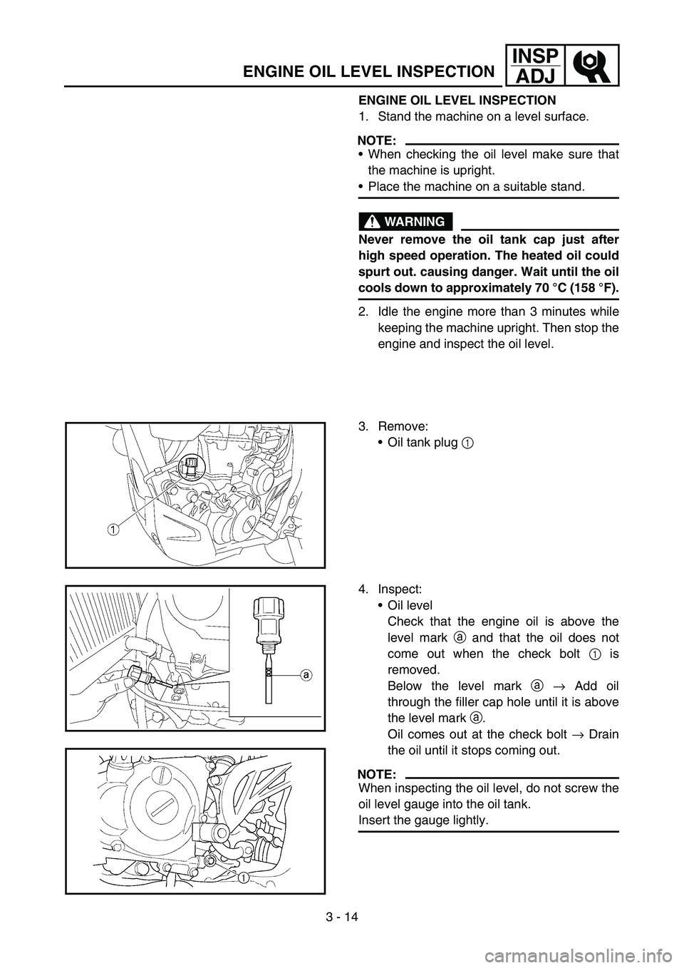
3. Remove:
Oil tank plug 1
4. Inspect:
Oil level
Check that the engine oil is above the
level mark a and that the oil does not
come out when the check bolt 1 is
removed.
Below the level mark a → Add oil
through the filler cap hole until it is above
the level mark a.
Oil comes out at the check bolt → Drain
the oil until it stops coming out.
NOTE:
When inspecting the oil level, do not screw the
oil level gauge into the oil tank.
Insert the gauge lightly.
Page 228 of 794

3 - 15
INSP
ADJ
ENGINE OIL LEVEL INSPECTION
(For USA and CDN)
CAUTION:
Do not add any chemical additives.
Engine oil also lubricates the clutch and
additives could cause clutch slippage.
Do not allow foreign material to enter the
crankcase.
(Except for USA and CDN)
CAUTION:
Do not add any chemical additives or use
oils with a grade of CD
a or higher.
Do not use oils labeled “ENERGY CON-
SERVING II”
b or higher. Engine oil also
lubricates the clutch and additives could
cause clutch slippage.
Do not allow foreign materials to enter the
crankcase.
5. Start the engine and let it warm up for sev-
eral minutes.
CAUTION:
When the oil tank is empty, never start the
engine.
Recommended oil:
Yamalube 4, SAE10W30 or
SAE20W40
Yamalube 4-R, SAE10W50
API service SG type or higher,
JASO standard MA
Recommended oil:
SAE10W30, SAE10W40,
SAE15W40, SAE20W40 or
SAE20W50
API service SG type or higher,
JASO standard MA
-20 -10 0 10 20 30 40 50
˚C 0 10 30 50 70 90 110 130
˚F
YAMALUBE 4(10W-30) or SAE 10W-30
YAMALUBE 4(20W-40) or SAE 20W-40
YAMALUBE 4-R(10W-50) or SAE 10W-50
-20 -10 0 10 20 30 40 50
˚C
SAE 10W-30
SAE 10W-40
SAE 15W-40
SAE 20W-40
SAE 20W-50
a
b
Page 230 of 794
3 - 16
INSP
ADJ
ENGINE OIL REPLACEMENT
6. Idle the engine more than 10 seconds
while keeping the machine upright. Then
stop the engine and add the oil to the maxi-
mum level.
7. Install:
Oil tank plug
ENGINE OIL REPLACEMENT
1. Start the engine and let it warm up for sev-
eral minutes.
2. Stop the engine and place an oil pan under
the drain bolt.
3. Remove:
Engine guard 1
Oil tank plug 2
Oil filler cap 3
Drain bolt (with gasket) 4
Oil filter drain bolt (O-ring) 5
Drain bolt (with gasket) 6
Drain the crankcase and oil tank of its oil.
Page 232 of 794
3 - 17
INSP
ADJ
ENGINE OIL REPLACEMENT
4. If the oil filter is to be replaced during this
oil change, remove the following parts and
reinstall them.
5. Install:
Gaskets
Oil filter drain bolt
Drain bolt (crankcase right)
Drain bolt (crankcase left)
6. Fill:
Crankcase
7. Install:
Oil filler cap 1
8. Inspect:
Engine (for oil leaks)
Oil level
Refer to “ENGINE OIL LEVEL INSPEC-
TION”. Replacement steps:
Remove the oil filter cover 1 and oil filter
element 2.
Check the O-rings 3, if cracked or dam-
aged, replace them with a new one.
Install the oil filter element and oil filter
cover.
T R..
Oil filter cover:
10 Nm (1.0 m kg, 7.2 ft lb)
Oil quantity:
Periodic oil change:
0.95 L (0.84 Imp qt, 1.00 US qt)
With oil filter replacement:
1.0 L (0.88 Imp qt, 1.06 US qt)
Total amount:
1.2 L (1.06 Imp qt, 1.27 US qt)
New
T R..10 Nm (1.0 m · kg, 7.2 ft · lb)
T R..20 Nm (2.0 m · kg, 14 ft · lb)
T R..20 Nm (2.0 m · kg, 14 ft · lb)
Page 234 of 794

3 - 18
INSP
ADJ
IDLE SPEED ADJUSTMENT
9. Check:
Oil pressure
Checking steps:
Slightly loosen the oil gallery bolt 1.
Start the engine and keep it idling until oil
starts to seep from the oil gallery bolt. If no
oil comes out after one minute, turn the
engine off so it will not seize.
Check oil passages, oil filter and oil pump
for damage or leakage.
Start the engine after solving the prob-
lem(s) and recheck the oil pressure.
Tighten the oil gallery bolt to specification.
T R..
Oil gallery bolt:
10 Nm (1.0 m kg, 7.2 ft lb)
EC35M021
IDLE SPEED ADJUSTMENT
1. Start the engine and thoroughly warm it up.
2. Adjust:
Idle speed
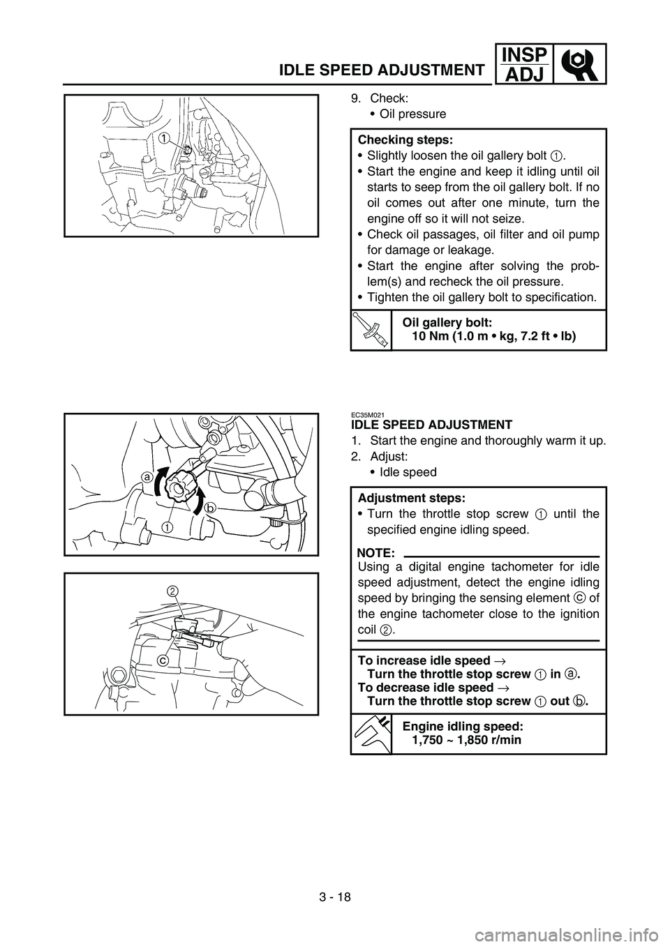
Adjustment steps:
Turn the throttle stop screw 1 until the
specified engine idling speed.
NOTE:
Using a digital engine tachometer for idle
speed adjustment, detect the engine idling
speed by bringing the sensing element c of
the engine tachometer close to the ignition
coil 2.
To increase idle speed
→
Turn the throttle stop screw
1 in
a.
To decrease idle speed
→
Turn the throttle stop screw
1 out
b.
Engine idling speed:
1,750 ~ 1,850 r/min
c2
Page 242 of 794

3 - 22
INSP
ADJ
6. Install:
All removed parts
NOTE:
Install all removed parts in reversed order of
their removal.Locate the rounded-off value and the mea-
sured valve clearance in the chart “PAD
SELECTION TABLE”. The field where
these two coordinates intersect shows the
new pad number to use.
NOTE:
Use the new pad number only as a guide
when verifying the valve clearance adjust-
ment.
Install the new pads 6 and the valve lift-
ers 7.
NOTE:
Apply the engine oil on the valve lifters.
Apply the molybdenum disulfide oil on the
valve stem ends.
Valve lifter must turn smoothly when
rotated with a finger.
Be careful to reinstall valve lifters and
pads in their original place.
Install the camshafts (exhaust and intake),
the timing chain and the camshaft caps.
Refer to “CAMSHAFTS” section in the
CHAPTER 4.
T R..
Bolt (camshaft cap):
10 Nm (1.0 m kg, 7.2 ft lb)
Install the timing chain tensioner.
Refer to “CAMSHAFTS” section in the
CHAPTER 4.
NOTE:
Turn the crankshaft counterclockwise sev-
eral turns so that the installed parts settle
into the right position.
Recheck the valve clearance.
If the clearance is still incorrect, repeat all
the clearance adjustment steps until the
specified clearance is obtained.
VALVE CLEARANCE ADJUSTMENT
Page 266 of 794
3 - 33
INSP
ADJ
DRIVE CHAIN INSPECTION
4. Inspect:
O-ring 1 (drive chain)
Damage → Replace the drive chain.
Roller 2
Side plate 3
Damage/wear → Replace the drive
chain.
5. Check:
Drive chain stiffness a
Clean and oil the chain and hold as illus-
trated.
Stiff → Replace the drive chain.
6. Install:
Joint 1
O-ring 2
Drive chain 3
NOTE:
When installing the drive chain, apply the lith-
ium soap base grease on the joint and O-rings.
New
7. Install:
Link plate 4
NOTE:
Press the link plate onto the joint using a
chain riveter 5.
Rivet the end of the joint using a chain riv-
eter.
After riveting the joint, make sure its move-
ment is smooth.
New
8. Lubricate:
Drive chain
Drive chain lubricant:
SAE 10W-30 motor oil or
suitable chain lubricants
Page 270 of 794
3 - 35
INSP
ADJFRONT FORK INSPECTION/
FRONT FORK OIL SEAL AND DUST SEAL CLEANING
Tighten the axle nut while pushing down
the drive chain.
T R..
Axle nut:
125 Nm (12.5 m kg, 90 ft lb)
Tighten the locknuts.
T R..
Locknut:
19 Nm (1.9 m kg, 13 ft lb)
EC36C000
FRONT FORK INSPECTION
1. Inspect:
Front fork smooth action
Operate the front brake and stroke the
front fork.
Unsmooth action/oil leakage → Repair or
replace.
EC36D001
FRONT FORK OIL SEAL AND DUST SEAL
CLEANING
1. Remove:
Protector
Dust seal 1
NOTE:
Use a thin screw driver, and be careful not to
damage the inner fork tube and dust seal.
2. Clean:
Dust seal a
Oil seal b
NOTE:
Clean the dust seal and oil seal after every
run.
Apply the lithium soap base grease on the
inner tube.