Page 356 of 616
4 - 46
ENGCLUTCH AND PRIMARY DRIVEN GEAR
Clutch
1. Install:
�Conical spring washer 1
�Thrust plate 2
�Primary driven gear 3
�Thrust plate 4
�Clutch boss 5
2. Install:
�Lock washer
�Nut (clutch boss) 1
NOTE:
Use the clutch holding tool 2 to hold the clutch
boss.
ÅFor USA and CDN
ıExcept for USA and CDN
3. Bend:
�Lock washer tab
Clutch holding tool:
YM-91042/90890-04086
New
T R..60 Nm (6.0 m · kg, 43 ft · lb)
Å
ı
4. Install:
�Friction plate 1
�Clutch plate 2
NOTE:
�Install the clutch plates and friction plates
alternately on the clutch boss, starting with a
friction plate and ending with a friction plate.
�Apply the engine oil on the friction plates and
clutch plates.
�Be sure to install a clutch plate with projec-
tion a offset approximately 90˚ from previ-
ous plates projection. Continue this
procedure in a clockwise direction until all
clutch plates are installed.
Page 358 of 616
4 - 47
ENGCLUTCH AND PRIMARY DRIVEN GEAR
5. Install:
�Ball
NOTE:
Apply the engine oil on the ball.
6. Install:
�Push rod 1 1
�Push plate 2
�Washer 3
�Nut (push rod 1) 4
7. Install:
�Pressure plate 1
�Clutch spring 2
�Bolt (clutch spring) 3
NOTE:
�Align the arrow mark a on the pressure
plate with the punched mark b on the clutch
boss.
�Tighten the bolts in stage, using a crisscross
pattern.
T R..6 Nm (0.6 m · kg, 4.3 ft · lb)
8. Check:
�Push lever position
Push the push lever assembly in the
arrow direction and make sure that the
mach mark are aligned → adjust.
aMatch mark on the push lever assembly
bMatch mark on the crankcase
Page 368 of 616

4 - 52
ENGOIL PUMP
Oil strainer1. Inspect:
●Oil strainer
Cracks/damage → Replace.
Contamination → Clean the flushing oil.
ASSEMBLY AND INSTALLATION
Oil pump
1. Install:
●Oil pump housing 1
●Outer rotor 2
●Inner rotor 3
●Pin 4
●Oil pump shaft 5
●Pin 6
●Oil pump cover 7
●Washer 8
●Circlip 9
●Conical spring washer 0
●Oil pump driven gear A
●Circlip B
●Screws C
NOTE:
●Apply engine oil onto the outer rotor, inner
rotor and oil pump shaft.
●Install the conical spring washer in the direc-
tion as shown.
2. Install:
●Oil strainer
●Gasket
●Oil pump assembly
●Screws (oil pump assembly)
NOTE:
Apply engine oil onto the crankcase oil pas-
sage and oil pump assembly.
New
New
T R..5 Nm (0.5 m · kg, 3.6 ft · lb)
New
T R..7 Nm (0.7 m · kg, 5.1 ft · lb)
NOTE:
● Install the oil pump drive gear with its groove
a facing the engine.
●Install the rotary filter with the dog b facing
out.
●Align the rotary filter dog b with groove c of
the crankshaft.
3. Install:
● Washer 1
● Oil pump drive gear 2
● Rotary filter 3
● Install the washer with stamped "H" for the
side of the engine.
Page 376 of 616
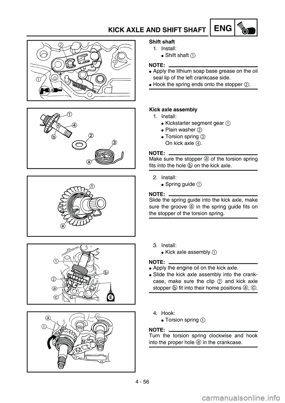
4 - 56
ENGKICK AXLE AND SHIFT SHAFT
Shift shaft
1. Install:
�Shift shaft 1
NOTE:
�Apply the lithium soap base grease on the oil
seal lip of the left crankcase side.
�Hook the spring ends onto the stopper 2.
Kick axle assembly
1. Install:
�Kickstarter segment gear 1
�Plain washer 2
�Torsion spring 3
On kick axle 4.
NOTE:
Make sure the stopper a of the torsion spring
fits into the hole b on the kick axle.
2. Install:
�Spring guide 1
NOTE:
Slide the spring guide into the kick axle, make
sure the groove a in the spring guide fits on
the stopper of the torsion spring.
3. Install:
�Kick axle assembly 1
NOTE:
�Apply the engine oil on the kick axle.
�Slide the kick axle assembly into the crank-
case, make sure the clip 2 and kick axle
stopper b fit into their home positions a, c.
4. Hook:
�Torsion spring 1
NOTE:
Turn the torsion spring clockwise and hook
into the proper hole a in the crankcase.
Page 378 of 616
4 - 57
ENGKICK AXLE AND SHIFT SHAFT
Kick idle gear
1. Install:
�Circlip 1
�Washer 2
�Kick idle gear 3
�Washer 4
�Circlip 5
NOTE:
�Apply the engine oil on the kick idle gear
inner circumference.
�Install the kick idle gear with its depressed
side toward you.
New
New
Page 380 of 616
4 - 58
ENG
EC4L0000
CDI MAGNETO (TT-R125/TT-R125LW)
Extent of removal:1 CDI magneto removal
Extent of removal Order Part name Q’ty Remarks
CDI MAGNETO REMOVAL
Preparation for removal Seat and fuel tank Refer to “SAET, FUEL TANK AND SIDE
COVERS” section.
Drain the engine oil Refer to “ENGINE OIL REPLACEMENT”
section in the CHAPTER 3.
Drive sprocket cover Refer to “ENGINE REMOVAL” section.
1 CDI magneto lead 1
2 Left crankcase cover 1
3 Nut (rotor) 1
Use special tool.
Refer to “REMOVAL POINTS”.
4 Rotor 1
5 Woodruff key 1
6 Pickup coil 1
7 Lead guide 1
8Stator
1
1
CDI MAGNETO (TT-R125/TT-R125LW)
Page 390 of 616

4 - 63
ENG
CDI MAGNETO AND STARTER CLUTCH
(TT-R125E/TT-R125LWE)
3. Check:
�Starter clutch operation
�Install the starter clutch drive gear 1 onto
the starter clutch 2 and hold the starter
clutch.
�When turning the starter clutch drive gear
counterclockwise ı, the starter clutch and
the starter clutch drive gear should
engage. If the starter clutch drive gear and
starter clutch do not engage, the starter
clutch is faulty and must be replaced.
�When turning the starter clutch drive gear
clockwise Å, it should turn freely.
If the starter clutch drive gear does not
turn freely, the starter clutch is faulty and
must be replaced.
Å
ı
1
2
EC4L5000
ASSEMBLY AND INSTALLATION
CDI magneto
1. Install:
�Stator 1
�Bolt (stator)
�Lead guide
�Screw (lead guide) 2
�Pickup coil 3
�Bolt (pickup coil)
T R..10 Nm (1.0 m · kg, 7.2 ft · lb)LT
T R..7 Nm (0.7 m · kg, 5.1 ft · lb)LT
T R..10 Nm (1.0 m · kg, 7.2 ft · lb)LT
2. Install:
�Stater idle gear 1
�Plate 2
�Bolt 3
�Washer 4
NOTE:
Apply the engine oil on the starter idle gear
inner circumference.
4
1
2
3
ET R..7 Nm (0.7 m · kg, 5.1 ft · lb)
Page 392 of 616

4 - 64
ENG
3. Install the starter clutch 1 on the rotor 2.
NOTE:
�Install the starter clutch with its plate portion
a facing the rotor.
�Insert the plate portion of the starter clutch
so that it is flush with the surface of contact
b with the rotor.
12 b
a
4. Tighten:
�Bolt (starter clutch)
NOTE:
Caulk a the end of the starter clutch holding
bolt near its outer diameter to serve as a stop-
per.
a
T R..30 Nm (3.0 m · kg, 22 ft · lb)
5. Install:
�Starter wheel gear 1
�Woodruff key 2
�Rotor 3
NOTE:
�Clean the tapered portion of the crankshaft
and the magneto hub.
�When installing the magneto rotor, make
sure the woodruff key is properly seated in
the key way of the crankshaft.
�Apply the engine oil on the starter wheel
gear inner circumference.
6. Install:
�Plain washer 1
�Nut (magneto) 2
NOTE:
Tighten the nut (magneto) while holding the
magneto with a sheave holder 3.
Sheave holder:
YS-1880-A/90890-01701
2
1
3
E
T R..80 Nm (8.0 m · kg, 58 ft · lb)
CDI MAGNETO AND STARTER CLUTCH
(TT-R125E/TT-R125LWE)