5 - 28
CHASREAR WHEEL AND REAR BRAKE
4. Inspect:
�Brake drum inner surface.
Oil/scratches → Remove.
OilUse a rag soaked in lac-
quer thinner or a solvent.
ScratchesUse a emery cloth (lightly
and evenly polishing).
ASSEMBLY AND INSTALLATION
Brake shoe plate assembly
1. Install:
�Brake camshaft 1
NOTE:
Apply the lithium soap base grease on the
brake camshaft.
2. Check:
�Brake camshaft operation
Unsmooth operation → Repair.
3. Install:
�Wear indicator plate 1
NOTE:
When installing the wear indicator plate to the
brake camshaft align the projection a on the
wear indicator plate with the slots b on the
brake camshaft.
4. Install:
�Brake camshaft lever 1
NOTE:
Install the brake camshaft lever in relation to
the punch mark a as shown.
T R..10 Nm (1.0 m · kg, 7.2 ft · lb)
5 - 69
CHAS
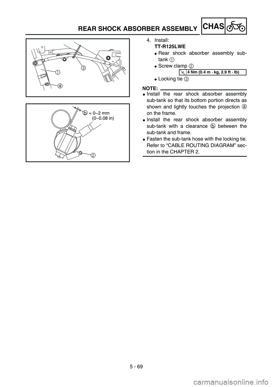
4. Install:
TT-R125LWE
�Rear shock absorber assembly sub-
tank 1
�Screw clamp 2
�Locking tie 3
NOTE:
�Install the rear shock absorber assembly
sub-tank so that its bottom portion directs as
shown and lightly touches the projection a
on the frame.
�Install the rear shock absorber assembly
sub-tank with a clearance b between the
sub-tank and frame.
�Fasten the sub-tank hose with the locking tie.
Refer to “CABLE ROUTING DIAGRAM” sec-
tion in the CHAPTER 2.
13
aT R..4 Nm (0.4 m · kg, 2.9 ft · lb)
b = 0~2 mm
(0~0.08 in)
2
REAR SHOCK ABSORBER ASSEMBLY